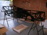
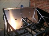
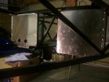
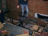
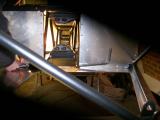
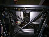
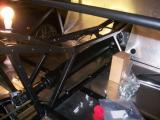
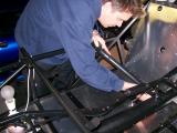
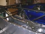
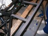
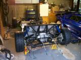
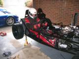
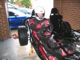
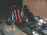
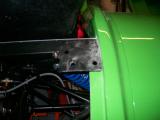
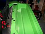
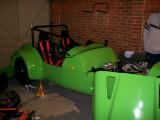
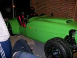
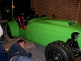
One of the factory options for a Westfield kit is to have the aluminium panels (that turn the space-frame chassis into a tub) pre-fitted. In addition to this, you can have the fuel and brake pipes fitted too, but that wouldn't be any fun now would it? The whole idea of the kit car was to build it, so we opted to do it ourselves.
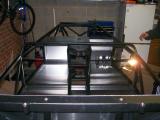
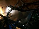
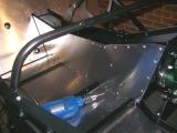
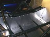
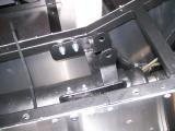
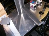
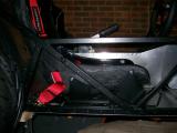
The panels must be trial fitted, clamped into place, drilled, removed, de-burred, refitted, sealed, and then riveted to the chassis. This must be done for the transmission tunnel (2 panels), the rear bulkhead, the front bulkhead (2 panels) the floor-pan (well over 200 rivets), and a couple of other panels had to be drilled and then removed until later on in the build.
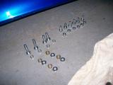
Before taking delivery of the kit, I decided to stock up on 4.1mm drill bits (Bosch ones seem to last quite well), and also buy an air compressor and air riveter to make light work of the riveting as the hand riveter method would probably cause R.S.I!
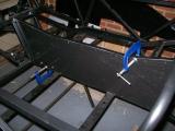
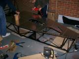
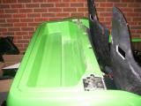
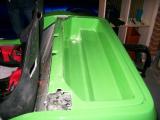
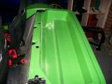
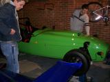
Matt and I set to work fixing and drilling panels. Once we got one panel drilled and riveted we quickly realised that it would be far quicker to use a drill each which meant we drilled twice as fast. Then once we removed the panel and applied the sealer, Matt would go round the panel inserting rivets and I would follow him with the riveter.
After doing a couple of panels, we found it best not to wipe the excess silicon sealer at all. Instead, just let it dry and it doesn't cause any smudging - you just peal it off.
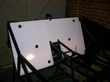
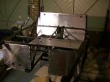
The floor-pan was the biggest job with so much drilling and riveting, but we managed all of the panelling in just one day. This was something I thought would take 2-4 days at least, but with 2 or 3 people you can plough through is very quickly. I wouldn't fancy it with a manual riveter though!
Laurence
 |
 |
 |
 |
 |
 |
 |
 |
 |
 |
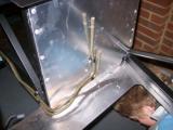
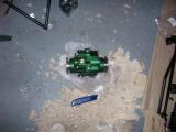
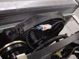
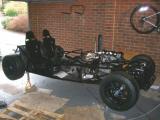
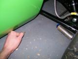
With the aluminium panels fitted, we could now begin to run the fuel lines from the rear of the chassis to the front. Westfield supply 2 pieces of pipe which must be bent to shape and then fixed to the chassis using rivets and P-clips (send and return).
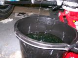
We set about bending the "send" fuel line first. We actually got a surprising amount of the pipe bent using our feet, the floor, and our hands, but then the 90 deg bend at the end went all wrong and the pipe flattened which would severely restrict fuel flow. The pipe cannot be bent back as it will become brittle and shear, so it was scrap!
DO NOT ATTEMPT TO BEND THE FUEL PIPES WITHOUT USING A PIPE BENDER!
We gave up early wasting a whole evening's work, and feeling very deflated knowing we would need to get hold of another fuel pipe from Westfield, and a Pipe Bender!
Laurence
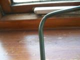 |
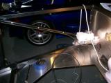
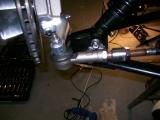
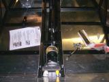
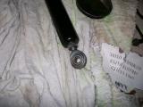
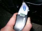
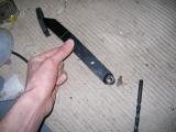
After the failed attempt at bending the fuel line yesterday, I went to Machine Mart first thing in the morning before starting work for the day and got hold of an automotive pipe bender (pictured below). It cost under £13 and looks like it will do the job nicely. I used it a couple of times on the scrap pipe which we damaged yesterday and it looks like it will work very well. Very tight, controlled bends, and the pipe cannot slip or rotate either. Excellent!
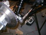
We began running the "send" pipe from the back of the chassis to the front. We went along marking with a pen, making 1 bend at a time, then re-fitting to check the next bend location. It's quite time consuming, but it's something you want to get right first time as your changes cannot be undone!
The pipe bender makes very light work of the bending and is especially good at making "S" shaped bends, where you need to drop the pipe down an inch (to clear the seat mounting holes for example). Eventually we had a shape we were happy with, and so we started drilling holes into the chassis, fitting P-clips around the pipe, and then riveting into place.
It quickly became apparent that all of the holes should be drilled BEFORE riveting the pipe into place other wise the drill-points become difficult to access, and it gets worse the more rivets you do as the pipe will be more reluctant to move.
The "send" line is now nicely in place, but we'll have to wait until Westfield send us a new pipe before we can run the "return" line. Luckily, we can move onto something else in the meantime as the fuel lines do not interfere with anything else at this stage.
Laurence
 |
 |
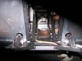
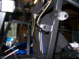
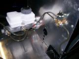
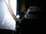
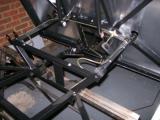
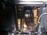
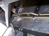
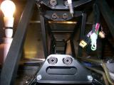
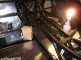
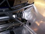
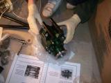
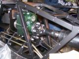
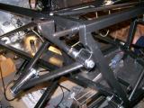
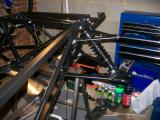
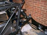
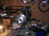
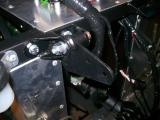
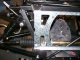
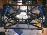
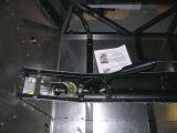
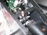
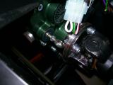
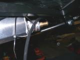
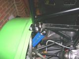
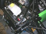
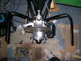
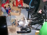
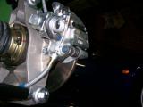
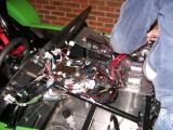
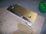
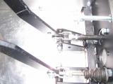
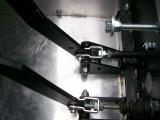
The AP Racing brake master cylinder was first to be fitted, on the other side of the pedals. Westfield had accidentally left out the nuts to secure this into place, so we just used some M8 locking nuts as a temporary solution. Also, the prefitted studs for the master cylinder to bolt onto do not exist as the manual states. Instead, you use M8 bolts (30mm I think). With this in place we ran the first brake line from the master cylinder, up the side of the chassis frame heading towards the front of the car, along the top of the frame and then it had to be bent downwards and back up into the bottom of the T-piece which was drilled and screwed into place. The brake pipe could comfortably be bent by hand and were then drilled and riveted into place.
Out of each side of the front T-piece, the smaller brake lines were ran along the front of the chassis frame where the T-piece was situated and bent in an S shape and left to hang by the holes next to where the front brake disks will be.
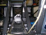
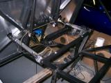
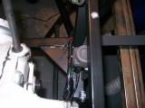
Another T-piece had to be drilled and riveted onto the same panel that the master cylinder sat on (behind the pedals). The smallest of all the brake lines was run from the master cylinder, into the side of this and then from the other side of the T-piece all the way down to the rear of the car, through the transmission tunnel (the opposite side to the fuel lines) and then to the T-piece at the rear of the car. The 2 smaller rear brake lines were then run opposite ways around the part of the chassis securing the diff and bent to where the rear brake disks will be situated. The brake pipes were drilled and riveted with the supplied P-clips throughout the car.
A word of warning: There is a small section of pipe that comes out of the secondary master cylinder port and into the T piece which you fit to the bulkhead. I would strongly suggest you fit the clutch master cylinder mechanism first, as the image in the manual tells you to run the brake pipe right into the route of the clutch master cylinder. It's much easier to fit the clutch MS FIRST, and then you can see exactly where you can run the brake pipe without fouling the mechanism.
Matt
 |
 |
 |
 |
 |
 |
 |
 |
 |
 |
 |
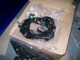
Tonight we had to back-pedal slightly to do some older jobs which didn't get finished, and then carry on with the wiring loom. The first job was to run the return fuel pipe. We damaged the first pipe by trying to bend the pipe without a pipe bender. DO NOT ATTEMPT THIS as you'll flatten the pipe. Westfield sent a replacement pipe yesterday, so we got to work on it first as you need to take your time with it.
We made the first couple of bends and then tried it on for size. We found that the more times you offer it to the car and then remove it to bend, the better it turns out. Once it's shaped, drill all of the holes before riveting any of the P-clips to avoid drilling through the pipe by mistake.
The pipe was not our best work, but looks good enough to not move, or foul any of the moving parts (I hope).
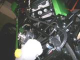
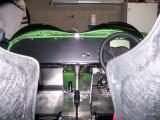
The next job was to fit the clutch master cylinder reservoir. There are 2 pre-drilled holes on the frame, but DO NOT use these as a) they are too big for a 4.1 rivet, and b) they are for the gear shift linkage. We riveted the bracket into place, and then screwed the reservoir into place. Westfield still have a few bits to send us, and one of them is the rubber pipe which sends the fluid to the clutch master cylinder.
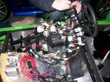
The last job of the evening was to finish the wiring loom. We got as far as feeding the fuse box wires through the scuttle panel, then found that the screws we needed (M5x25mm) were missing, but Westfield have now sent them. The loom must be separated into front and rear, then you can begin fastening the loom to the chassis.
The only complicated bit was working out how to fix the loom to the underside of the transmission tunnel when a drill was nowhere close to fitting in the gap. Eventually we decided to drill from the top through both sides of the chassis rail. This forms a straight and neat hole at the bottom, and the hole at the top of the rail will just get covered up by the panel and the trimming.
We followed the guide and fixed the loom all the way to the rear, but we have left off the last few loom fixings until the diff is in place, since the ATB diff we opted for is different to the one pictured. When we can see how it fits we'll decide the best route for the last 2 feet of the loom to follow.
Fingers crossed the diff and reverse box will be here by the end of the week...
Matt
 |
 |
 |
 |
 |
 |
 |
 |
 |
 |
Yes, it did turn up before Christmas, everything required did, much to our relief...just the exhaust and digital dash are still to come now!
After running the wiring loom correctly around the car and to the rear through the drivers side of the transmission tunnel we just finished it off after a trial fit of where the diff would sit just to see where best to run the final part of the loom right across the rear from drivers side to passenger side. The clearance is huge between the diff and loom so we went ahead and drilled the required holes and riveted the clips and then left the cable ties loose just in case things needed a last minute adjustment. What we deemed to be daunting (the wiring loom) turned out to be very, very straightforward thanks to how neatly the wiring comes.
Anyway the diff....
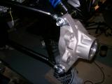
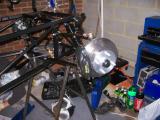
A late start today as Laurence got back from a weekend in Dublin late, so not much of an opportunity to get much done. The diff is fairly heavy - heavy enough to be awkward to get in position without scratching the chassis or a brake pipe, but its not overly heavy. I just lifted it into position and Laurence put the rod studs through the holes to support it whilst we found the necessary nuts to tighten it and then it was literally a case of just tightening and torquing it up. Fairly straightforward job. It was very cold tonight, so we just left one of the propshafts until tomorrow!
The diff stud nuts have a habit moving down the thread on one side, but not the other, leaving the stud unevenly spaced. The best way to stop this happening is to tighten one side to where you want the bolt to finish on the thread, then put another nut on behind it. You then tighten this nut against the other and this will prevent the nut from moving any further down the thread - allowing you to tighten the other side easily.
Matt
 |
We were going to crack on with the rear wishbones today, however, 3 of the wishbone threads had been tapped by Westfield as requested by us, but one had not and we did not have a tap (1/2 inch UNF) so we were in a spot of trouble. This thread also managed to damage 2 rose joint threads too! But as we were at a stage where numerous parts could be done in any particular order we chose to crack on with the propshaft from the rear differential upto where the reverse box will sit. Once again this was a case of putting it the right way round and tightening it up. However its never quite that easy, it took most of the time to find the right bolts and then trying to torque the bolts up with the transmission tunnel in the way proved very awkward too. However it didn't take long and it was in, next was the reverse box.
Christmas Eve being Christmas Eve, we started late and had to pack up early as a night on the town was in order.
Merry Christmas and to be continued.....
Matt
 |
 |
 |
 |
With the family round all day yesterday and today we were struggling to spend too much time on the car but we got a little bit done. First off it was our uncle Alan to the rescue who brought his tapping tool round and attacked the dodgy thread with nothing but a successful outcome. He used to run an automotive engineering firm and had seen many problem threads before. He cleaned up the thread on the offending wishbone first, and then both of the rose joints in just a matter of minutes. All sorted now - each rose joint threads up beautifully..
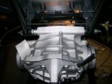
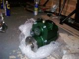
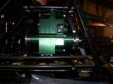
We just spent a little bit of time on the Westfield Reverse Gearbox. Opening the bubble-wrap it is a lovely bit of kit, and fairly easy to fit too. The supports had to be put on the reverse box (off the car) but they had to be left loose to allow the rods to get all the way through much easier. The detachable reverse gearbox mount (the front and bottom mount) had to be removed and then we held the reverse box into position (Westfield logo facing the rear of the car) and put the 215mm rods through the gearbox brackets and then put the detachable mount back on the car once the rods had gone through them. Once equal thread was showing at both ends, nyloc nuts and threadlock were put on and everything tightened. It takes a bit of polite force, but with enough slack in all of the fixings you can get it all to line up, and then just tighten each of the fixings.
Then we secured the prop already attached to the diff (the longer of the 2 propshafts) to the reverse gearbox. Torqued them up and then it was time to call it a day and back to Boxing Day family time.
Over the next couple of days there should be some major progress with the front propshaft, front and rear suspension, front and rear hubs and front and rear brakes.
Matt
 |
 |
 |
 |
 |
 |
 |
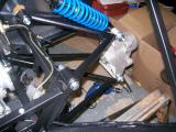
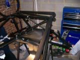
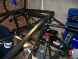
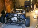
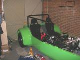
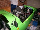
I had decided not to work between Christmas and New Year and set aside most of the time for working on the car. Today's job would be fitting suspension and wishbones. We were both looking forward to this, as up until now it didn't look like much had happened to the car, but after today it would look like a car instead of a bathtub.
I started on the rear section first. Lots of copper grease on all of the threads and moving parts and then the top and bottom wishbones can be bolted into position. The entire setup should only be finger tight until the car is finished (to aid the geo setup I presume). Many visitors have since commented on "That bolt not being tight!" :)
After getting both sets of wishbones on, and then realising that the uprights would not fit, I realised that I had fitted the lower wishbones upside down, so off they came, and they were refitted the correct way and everything lines up beautifully. I had to enlarge one of the holes in the rear bulkhead panel to get full access to a bolt, but other than this it's very straightforward.
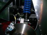
It was now time to fit the suspension dampers. We were supplied with 2 pairs of front suspension - one with blue springs, one with black. After an hour of looking on the web for the difference and finding nothing, I decided to "get technical" and compress the dampers to see which was fitted with a higher spring rate. The black springs were much harder than the blue, so they must be the front units. I then looked through the item list and it listed "shock absorber std front", and then "shock absorber bike front" so I am happy that both front and rear dampers are "front" units on this kit. Further down the parts list I see "SPRING 7x200x2 BUS/NTR FR BLK" so I am happy that the black set go on the front.
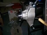
With these bolted the next job is to fit the driveshafts, but we quickly run into a problem. The nearside stubshaft does not fit through the hub. We have given it to a friend to see what they think, and he has agreed that there is something wrong with it - the splined shaft seems to be the wrong size! The offside unit fits just fine, but we can't fit it tinto place because the driveshaft bolts are missing from the kit. We'll ring Westfield when they are back from their Christmas break on the 2nd January.
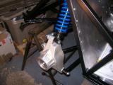
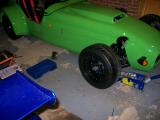
It's now time to fit the front suspension to the car. More copper greasing, and the front wishbones can be fitted and the dampers bolted into place. We decided at this point to fit the front brakes as the AP's take up a box by themselves and it would be good to get rid of it, so the ball joints were fitted into place. We had to get some extra bolts as the size stated for the lower ball joint will not fit the Megabusa chassis. Once they were bolted down we fitted the front uprights, discs, and calipers - again, finger tight for now.
With the shock absorbers bolted into place it looks much more like a car. However, from this stage you should watch your head when under the car it's very easy to whack your head on a disc when standing up. You'll see what I mean!
Laurence
 |
 |
 |
 |
 |
 |
 |
 |
 |
 |
 |
 |
 |
 |
 |
 |
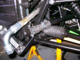
Today I set to work fixing the steering rack into place since we couldn't fit the rear brakes until the drive shaft bolts were sent. Following the SEi manual, I fitted the rubber mountings to the rack. I didn't have any silicon lubricant, so I used a bit of washing up liquid as rubber does not object to this. With the washing up liquid and a rubber mallet, the metal clamps fitted over very easily. I bolted these down and then span the track rod ends into the shaft.
When I fixed the track rod ends to the steering arms on the uprights I knew something was wrong. Both wheels were pointing inwards and then I remembered that we has specified the wider front track option. This means the front wheels are further apart from each other, and then steering rack was not wide enough. I was thinking that Westfield had sent the wrong rack, but were closed for a couple of weeks so I couldn't ring them. I returned to the house quite annoyed, and then though there was no way that Westfield would develop an entirely new steering rack for this upgrade, so I began looking around for something that would extend the steering rack, and I found them almost immediately. Without instructions, I fitted them along with a nut each side, and it seems right. The steering is still not straight, but we can fully adjust the tracking once the car is ready to be driven, and do the camber adjustments at the same time.
The last job today is the front propshaft, which connects the drive from the engine to the front of the reverse box. Looking at the torque values for these nuts, I realise they must be thread-locked too which I didn't do for the other bolts, so I decide to go back and do each of the other bolts at the other end of the reverse box, and also the rear diff too. In addition, I fitted a spring washer to each as a double precaution. You will reach a point where the torque you apply will spin the propshaft instead of torquing the bolt. At this point you should stick a screwdriver into the propshaft joint. When the screwdriver meets the chassis it will wedge and allow you to torque the bolt.
I marked each of the bolts with a line so we can see if they move at all, but I doubt they will. The only thing to worry about is if the tensile strength is high enough, but I think the driveshaft bolts will be the only ones to possibly worry about as they are situated after the 3.3 final drive and not before it.
Laurence
 |
 |
 |
 |
 |
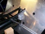
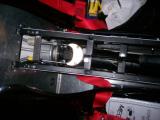
Just a couple of hours spent on the car today. We fitted the handbrake lever which requires the drilling of two large holes in the two cross-members in the transmission tunnel, and then just needed bolting down.
We looked at the diagram for ages trying to work out which bracket the handbrake cable is supposed to pass through, and then gave up. (A later phone call to Westfield revealed that the bracket is in fact missing from our chassis and they are sending us a bolt-in section to correct this).
The chassis was still covered in swarf from day 1 of the build, and we were about to fit the transmission tunnel panels which also required sealing. They had already been drilled from day 1 of the build, so we decided now was a good time to vacuum out the swarf.
Once this had been done, we sealed and riveted the centre panels.
With the panels in place, we could drill through them and into the gear shift bracket. The manual says this bracket should not protrude above the transmission tunnel, so we did it level with it thinking this would be best. (It turns out this was still too high as the rod later fouled the top of the chassis by the fuse box. We have had to order a new bracket as we couldn't re-drill the original.)
We fixed the quadrant to the chassis next to the clutch fluid reservoir and then finished up there.
Laurence
 |
 |
 |
 |
 |
 |
 |
 |
Despite not being able to fit our driveshafts due to one of the stub shafts being wrong, we decided to fit the fuel system, but just not secure the tank into place so we still had lots of access to fit the shafts once they became available.
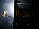
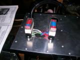
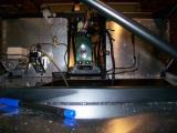
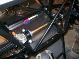
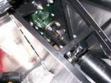
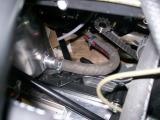
Following the Megabusa manual instead of the SEi manual, task number 1 was to fit the fuel inertia cut-off switch to the chassis. This gadget is responsible for cutting the power supply to the fuel pump in the event of a sudden impact.
Dan had come round to help us this evening to finally earn his part-timer status (and also because he hadn't even seen the car up until now). After a bit of head-spinning, we worked out where the inertia switch was supposed to be fixed, so we drilled the holes into the chassis and then secured the switch into place. Make sure you leave enough room to be able to press the switch down as there is a chassis rail directly above it! Once in place we connected it to the wiring loom as per the instructions.
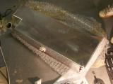
The tank is situated on the back of the chassis, but foam tape must be laid so the tank sits on a soft base rather than bare metal, because the movement could wear the tank over time. We laid foam tape everywhere the tank will be in contact with.
The same applies for the tank straps that secure the tank into place. The manual states that 1 inch tape must be used, so we just doubled up the 1/2 inch tape we had. It's easiest if you pull off the tape backing just a few inches ahead of the section that you are sticking so you can "steer" the tape.
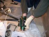
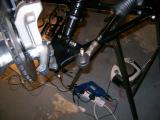
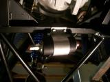
Now on to the fuel pump. The pump sits a little low for my liking, but I was only following what the manual says! You will need two people for this. It's easiest to mark the chassis and then drill right through from there, then get a second person to guide the bolt through the chassis. Also, the fuel pump has a foam sleeve which it sits inside before fitting in the bracket. Use washing up liquid get it in otherwise you'll be there all day.
Once clamped down, the pump can still move a little, but the fuel hoses will prevent this movement once connected. You now need to secure the fuel pump section of the wiring loom to the chassis and then crimp some connections to connect the pump to the loom. Once we had done this, we fixed the fuel pump nipples into place - largest at the rear (low pressure in), smallest at the front (high pressure out), and then connected the fuel pump "out" to the fuel send line, and then covered it in a plastic sleeve. There are several different types of fuel hose used for this section - make sure you use the right one!
We have left the rest of the fuel piping until the tank is fitted. Once the driveshafts have been fitted the tank should drop in without any fuss at all.
Laurence
 |
 |
 |
 |
 |
 |
 |
Just a couple of little bits today as we're still waiting for parts before we can continue on the main stuff, so we thought we'd clear some of the more minor jobs that will no doubt add up at the end if we don't.
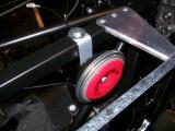
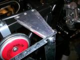
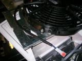
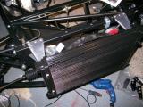
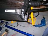
One of these is the radiator. Be warned - the SEi manual bares almost no likeness to the Megabusa radiator, and neither does its fitment! I had already looked at it previously and gave up. Earlier in the week I had rang Mark at the factory to find out more about it, and he told me that it mounted to a separate bracket which is why I couldn't work it out. He send me some pictures through which I have attached below.
You need to:
- Mount the radiator plate to some brackets.
- Rivet the brackets to the chassis when you are happy that they are evenly spaced
- Remove the plate from the brackets.
- Fix the fan inside the plate
- Re-fit the plate
- Fix the radiator to the plate.
We found that the easiest way to drill the bracket holes into the chassis was through the brackets themselves, that way the hole was already aligned with the hole in the bracket. Very easy, and then just 6 rivets to fix.
I got all of this done, and then couldn't work out which bolts to use as they all seem too long for the radiator thread, so I leave the radiator off. Probably a good idea actually as the chassis will be lifted down off the stands soon, and the radiator will probably be in the way.
Now that the radiator brackets were fixed, we could fit the horn without fear of it overlapping the rad brackets, so back out came the drill. We had to bend the horn bracket, but it was best to use the chassis rail we were mounting it to, which gave a perfect bend. Once fitted into place I couldn't resist putting a battery across it - "Beep Beep" :)
Laurence
 |
 |
 |
 |
 |
 |
 |
 |
Westfield sent a new stub shaft to replace the nearside item that didn't fit. However, they have sent me an offside shaft. So now I have 2 offside shafts. No point doing anything today, and I leave the garage very annoyed!
Laurence
Back over Christmas we discovered that our nearside stubshaft didn't fit through the hub, and Westfield got another one to us a week after New Year. Unfortunately they had send us another offside instead. When I contested this with them they told us they had sent us a nearside! Hhhhhhmmmmm.......
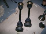
After a bit of talking and checking, we worked out that the manual was wrong. The SEi manual states that the nearside has a white nut with a reverse thread, but it is infact the offside that should have this driveshaft, as the nuts must be tightened in the opposite direction to the wheel rotation! Makes sense now.
So Westfield did in fact send the stub shaft that I asked for (nearside), and I had asked for the wrong one, but this is only because their manual is wrong. At the time of writing, page 66 of the SEi construction manual is wrong. The nearside driveshaft outer (stub shaft) has a conventional thread and is fastened with a green nut. The offside has a reverse thread and is fastened with a white nut.
This still doesn't help my situation though. I still have two conventional threaded stubshafts, and on top of this I have to swap the stubshaft I have fitted on the offside to the nearside, which means removing the brakes and the drive shaft. Westfield parts are extremely good though and sorted it out very quickly once they realised what the problem was, and the correct one will be with me this week.
Laurence
The correct stubshaft is now here along with a few other bit, so tonight I have to remove the one I have fitted in the offside, and fit it into the nearside (see previous post). This means removing the driveshaft and also the rear brake assembly. In the end I didn't have to remove the driveshaft - I just disconnected the outer end from the stub shaft and then disconnected the upright to allow it to pass through.
Once this was done, I swapped the new stubshaft in and through the upright, and connected it all back up again. I then fitted the stubshaft on the other side, fitted the driveshaft and then the brakes.
The last thing to do this evening was torque all 24 of the drivehsaft bolts up using threadlock. This is quite time consuming because there is not much room to work with, and the handbrake is still slack so the wheels begin to turn before you reach your torque limit. The easiest way to combat this is to fit a rear wheel which you can hold whilst tightening which will prevent the driveshaft from turning.
Unfortunately I forgot to take any pictures :(
Laurence
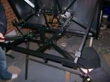
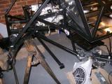
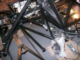
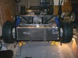
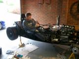
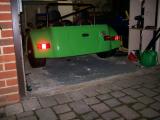
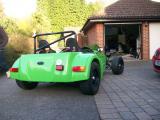
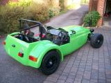
This is the day that Matt had been waiting for, and it had finally come. Everything that requires the car to be waist-height had now been ticked off the list and the car could now be dropped to axle stands so the engine could be dropped in.
We had set aside Saturday the 19th Jan for several people to come round and help. There were several methods we talked about to get the car down from such a height to the floor, but eventually we decided that the bast way was just to get a team of people to help lift it down manually.
However, between the last session and today, I realised I had used Loctite threadseal and not threadlock on the driveshaft bolts. I assumed that the yellow Loctite tube supplied with the dry sump kit was threadlock, but luckily I checked and it's threadseal instead! What this does mean is that each bolt needs to be removed, cleaned, threadlocked, and refitted. The bolts really weren't locked at all though. To speed up the process I removed one, gave it to Kriss to clean the threadseal off, and fitted the previous one whilst I was waiting each time. I used Loctite 243 which is oil tolerant, and ideal for this application as the bolt passes through grease before locking in the thread.
Whilst I finished this, Matt fitted the aluminium panels that cover the reverse box.
Now on to the main event. The team was formed - Laurence, Matt, Kriss, Marky, Terry, and Lauren. We had 2 options, the first being to lift the car down from the stands straight onto axle stands, and the second being to fit the wheels, lift the car down to the floor, and then jack it up onto axle stands. We decided the second option was the best, and besides, Matt couldn't wait to get the wheels fitted anyway.
With this done, we positioned myself and Matt side by side at the rear of the car, Marky and Terry either side, and Kriss at the front. On three we lift the chassis, and between 5 of us it was very easy indeed. Lauren pulled each of the chassis stands clear, and we gently lifted the car down to the floor.
Matt's face had lit up - he had lost a lot of enthusiasm for the project with parts not turning up, and the arrival of his (Playstation 3), but now he could see it was really looking like a car, he was back in love with the idea of it all again.
We got out 4 axle stands, set them to their highest setting, cut some timber to the width of the chassis, and then just picked up the front of the car and set it down on the axle stands, using the timber to spread the load across the chassis. We then did the same for the rear end.
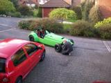
Seeing the car on the floor made the whole project seem real all of a sudden. The car is so low, and the funniest thing is how high it made the Noble M12 next to it look. It's not often you'll hear that said!
...and still to this day, Matt cannot take a photo that is in focus, so I'm very sorry, but you'll have to make do with what's here!
Laurence
 |
 |
 |
 |
We fitted the handbrake with relative ease, but we could not work out how to fit the cable. Mark at the factory sent me several pictures, and I eventually concluded that the securing bracket must have been left off the chassis by mistake. I sent Mark an image, and he confirmed that this was indeed the case.
Mark got the fabrication guys to create a bracket, and in order to fit it, we had to drill through the chassis on both sides, and secure it underneath (normally this would be welded into the chassis from the beginning). In addition to this, I opened up the holes slightly to we could use countersunk screws instead of bolts. We made quite a nice job of this. It's just a shame the bracket wasn't powder coated, but it wouldn't be hard to swap a new one in at a later date, or even remove it and powder coat it ourselves.
Now this was in, we could fit the handbrake cable through it, and onto the rear brakes. You follow the route that the manual shows you, cable tie in a couple of locations, fix to the calipers, and then fix the bracket to the handbrake using a clevis pin and a split pin to secure. We give it a quick go and it works, although it will need adjusting before driving.
There is a grommet situated on each side of the handbrake cable near the caliper. Snip this off as it's not required for the Westfield. Also, you will see some blue sleeves on the cable - these should be used underneath the cable ties.
Now that the rear end is completed, we could drop the tank into place. We had done all of the preparation on the tank already (see earlier post), so all that remained was to put the tank in and strap it down. Ours is the long range version. The tank doesn't feel that secure, and moves around a lot, both forward, back, left and right. I wonder if this could be tighter?
Laurence
 |
 |
 |
 |
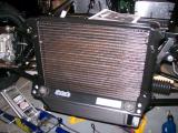
Westfield had to send me through a couple of images to help me do this, which are attached further back in a previous post. I had already fixed the brackets into place, but couldn't find the correct bolts to do the rest.
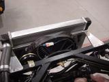
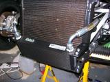
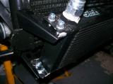
It turns out that you have to use 4 M6x20mm hex head bolts and use a spring washer and a plain washer to space it out a bit so it doesn't hit the bottom of the radiator thread, so the sequence (from behind the radiator) is: bolt, spring washer, plain washer, radiator bracket, radiator plate, radiator.
3 bolts went in fine, but the bottom nearside wouldn't go, so I had to take it all off, and then knock the lower bracket over with a heavy mallet. Now it lines up perfectly, so I refit and tighten each bolt.
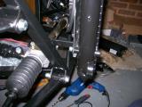
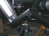
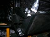
Now the oil cooler can be fitted into place. It's a little hard to see in the pictures, but there are 4 black brackets - two are fixed at the top, and 2 at the bottom. You fix the lower brackets (larger) to the lower suspension wishbone, and the upper brackets (smaller) to the radiator. I had to jack up the wheels a tiny bit just to take the weight off the wishbone bolt to remove it.
Do this loosely, and then you can get the oil cooler into place (oil pipe connections at top). The brackets go ABOVE the oil cooler mounting points for both upper and lower brackets (pictured). The lower brackets look like they could do with a spacer fitted, but I can't find anything suitable, so I just tighten anyway and they seem really secure.
Laurence
 |
 |
 |
 |
 |
 |
 |
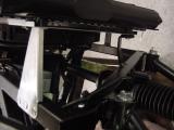
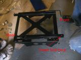
I had looked at the seats many times, and just got confused by the parts and fixings. This is another area that is left completely up to your imagination, as it's not in either manual. I spoke to Mark at the factory about them, and I have a pretty good idea what to do.
It was a bit of a gray area, so I'll explain how you do it here.
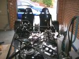
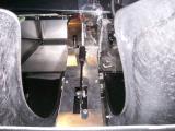
The first step is to fix the runners to the sub frames. Although the sliders are present, you still have options on how far forward or back the seats can be fitted, so you slide a few inches forward and back of a base location. Matt and I are both just over 6ft, so we decided that the base location should be as far back as possible, so we used the forward-most holes on the sub frame as our fixing points.
You also need to poke a bolt through each of the seat sliders. There is a stud at the rear of each slider, so you need to fit the bolt at the front of each.
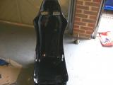
The seat can now be placed into the sub frame. My pictures don't make it very clear, but the front of the sub frame higher than the rear, so when the seat is placed in the frame, is is automatically rocked backwards slightly. Place the sub frame on the floor and sit in the seat to make sure the seat is squashed fully into place. We did this, and when we were happy, you drill the front seat holes. The holes are already present in the frame, so you just need to follow them through into the seat with a drill.
Once we did this, we bolted the front of the seats to the frame. You use a large dome washer which has a nice recess for the countersunk bolt on the inside of the seat so the bolt doesn't poke into you.
The sequence is (from inside of the seat outwards): countersunk bolt, large dome washer, seat, sub frame, small washer, nut. Now the front of the seat is fixed, but the rear has movement, so you can adjust how steep the seat is.
To do this, fit the seat into the car. You will need to drill through the aluminium in the car - you'll see exactly where as the holes are already there on the seat mounting points. Just make sure you drill through the correct holes, as there are more than one set. On out chassis it was the inner set of holes.
With the seat sitting in place, jump in the seat and make sure you are happy with the angle. You can adjust it by placing bits of wood between the seat and the sub frame to raise it, but we were happy with how the seat fits when resting at the bottom of the frame - it gave us the perfect angle. We removed the seats from the car, drilled the rear holes into the seats, and then fastened in exactly the same way as above.
Finally, we re-fitted the seats and bolted them into the car. You will need to use a large washer under each bolt so it rests between the bolt, and the underside of the floor-pan. To tighten the front bolts you will need to slide the seat back and put an Allen key into the bolt to stop it spinning.
This was even more exciting than the engine going in, because we could finally sit in our car and visualise it. Matt got a bit carried away with it all though - see photos!
Last job is to fit the harnesses into position. We have 2 sets of harnesses, but only one fixing kit, so we'll have to call Westfield about the missing kit. Anyway, the bottom of the harnesses bolt into the side of the frame using the supplied bolt, a washer, and a locking serrated washer. The tops just clip into eye bolts which must be fitted just behind the headrests with the supplied spacer.
Laurence
 |
 |
 |
 |
 |
 |
 |
 |
 |
 |
The reverse box had been installed for some time, but the linkage to set the reverse box into forward or reverse had not been installed, so this was the first thing I wanted to tackle tonight.
The bracket must not stick up above the rail, but this was difficult since the bracket is taller than the rail and the mounting holes are too near the bottom of the rail to drill into when the bracket is pushed level with the rail, so i decided to enlarge the bracket holes slightly so that it would sit lower. This gave an extra mm clearance and the bracket will now sit nicely.
I drilled through both sides of the chassis rail at the lowest point possible. This was easy for the hole on the right, but the left hole had to be drilled at a big angle so it was quite difficult. I removed the bracket, fitted the lever and mounting bush, and bolted it into place. Remember to put the bracket mounting bolts in first!
The bracket bolts nicely into the chassis rail, so now it just needs connecting up. I fitted the rose joints into the rod and then bolted them into place. It was just a case of trial and error with the length, and more importantly the clearance of the prop when in reverse. It's fine when in forward gear, but quite close to the prop in reverse. Hopefully it should be ok though.
Now I moved on to the fuel tank plumbing. There are a couple of inserts for the fuel tank which need bolting in for the fuel hose to attach to, then just a case of following the lines that the manual suggests and securing. I used quite a bit of protective tubing in case there is any movement.
Whilst I did this, Matt tackled one of the outer aluminium panels which seal the outside of the car. The only problem was that my air compressor had broken. Matt said he was quite happy to do it by hand though. He got 3/4 of the way through them, and then caught his thumb between the handles which put him out of action for the rest of the evening. It would hurt under any circumstances, but with the cold as well, it hurt him twice as much. I finished the last few off before the silicon dried though even though I didn't want to.
After just a few my hands really hurt. I'll buy another compressor tomorrow and do the other side with the air riveter. I'm not going to damage my hands anymore!
Laurence
 |
 |
 |
 |
 |
I got my new compressor today, so we could fit the remaining side panel into place this evening with the aid of an air riveter. 15 minutes later the job was done! The air riveter just makes such light work of it all. Apart from fitting the 2nd side panel into place I had set tonight aside for a few odds and ends that needed attention. The one that was annoying me the most was the stud that goes through the lower frame of the engine. These studs have a habit of threading on one bolt, but not the other because they spin the entire stud through the opposite nut to the one you want to tighten., so you end up with a load of thread sticking through one bolt, and none through the other meaning the nyloc cannot do its job.
There are a few ways around this, but there is such little room on this stud that the only way I could get the stud evenly spaced was to remove the stud, place a nut on one end, and fit a nut that was too small for the thread on the other. Now when you tighten both bolts towards each other, the smaller bolt locks against the thread, and allows you to tighten the other through the nylon - WINNER!
The other odd job that was annoying me the 2nd most was on the differential. There is a 16mm spacer which spaces the diff on the upper stud, but we originally couldn't find this so we used M12 washers and later needed those washers. The spacer was in a clear plastic bag with all of the pedal bushes, gear shift rose joints, and other bits. It was annoying me, so I changed it.
Both diff studs needed slackening, and the top one removing (which meant the brake pipe T-piece had to be removed). I then had to loosen the driveshaft nuts, and the bracket that secures the diff at the rear. The diff needed levering over with a pry-bar to make room, and after about an hour of struggling, hammering, levering, and swearing, my Dad and I finally got it into place and tightened everything up.
The last thing I wanted to do tonight was fit the remaining 2 fuel hoses - one from tank to fuel pump, and the other from return line to tank. I cut the pipes to length, cable tied them up with the wiring loom, and then placed the protective tubing over the top. The garage is a total mess with tools and bits everywhere, so before I finish I had a good old tidy-up ready for next time. We are very close to starting the bodywork now.
(Again, I forgot to take pictures!)
Laurence
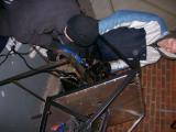
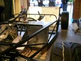
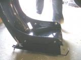
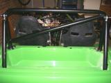
Tonight Matt and I both had the evening to work on the car. I wanted to get the coolant plumbing done, and Matt wanted to get the roll bar fitted, so we worked at opposite ends of the car and helped each other when required.
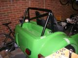
The main bodywork section has a square tab which sits on top of the standard roll bar mounting points, but the RAC bar bolts directly onto the supports, so we cut the tabs off. The boot box requires cutting into as the support bars for the roll bar pass through it, so it's just a case of trial and error with the marking and cutting.
Before this could be done, Matt has to cut some holes into the boot box so that the top harness eye bolts could sit into place. He measured where these needed to go and then cut them with a hole saw. They were almost perfect first time and the harness bolts sit really nicely in place. We'll need to get some grommets for the spacers to tidy up the holes eventually though.
Now we bolted the roll bar into place. You get a giant bag of nuts, bolts, and washers, and you need to use the 6 shortest Allen head bolts, 6 washers, and 6 nylock nuts to secure the main section of the roll bar into place. One of the bolts is difficult to get into place as the cross bar is very close to it, so we used an Allen key bit and a spanner - a rachet was far too tall.
Now we held the support bars into place and marked where the bars touched the bodywork as these sections needed to be cut slightly. They don't need to be too neat though as the boot box will cover them.
Now for the hardest bit - cutting the holes into the boot box itself. This is really difficult as you have to cut through corners at an angle. We fitted the bars into place, made some marks and measurements of where the bars started and finished, and translated these marks into the boot box which described a line to cut. Matt did very well with the hacksaw. The lines are not that neat and will definitely need smoothing and finishing, but I was very impressed overall. He stuck with it well, and the roll cage looks awesome!
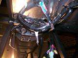
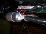
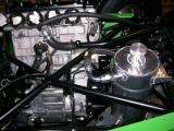
Whilst all this was going on, I was sorting out all of the coolant hoses. Westfield supply some hard pipes, and some rubber hoses too, and I had to get some images sent to help me out. All of the images I took have come out really dark. I have lightened them in Photoshop so hopefully they will be clear enough.
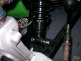
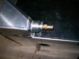
The two rubber hoses have a bulge at one end and and reduce down. The bulges fit on the radiator connections and then onto the solid pipes. You cut these pipes to length and then use the other half on the opposite end of each of the solid pipes to connect to the engine.
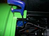
The top radiator connection goes to the slightly angled hard pipe, and then connects to the thermostat. The bottom connection goes into the 90 degree hard-pipe, which then curves right round the back of the engine near where your fuel pipes terminate on the passenger bulkhead. From here you use the rest of the rubber hose which you cut and connect it to the engine (very near the water pump). I couldn't get any pictures of this, but Westfield have some which I attached.
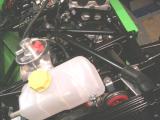
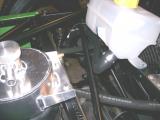
There is also a lot of plumbing to do with the header tank. The large outlet which points to the oil tank connects to the lower hard pipe using the supplied rubber pipe. If they seem tight, stick them in boiling water to make them a lot more flexible and they fit really easily. You need to cut this pipe to length and then push it over the stub on the lower pipe (pictured).
There is a final outlet on the header tank which points to the offside front wheel. You need to cut some rubber pipe (I used fuel hose which is what was used in Westfield's pictures). This pipe goes from the outlet to a T-piece. This T-piece then needs 2 further pipes coming off it. The first connects to the top of the thermostat (just above where the first hard pipe finishes). The last t-piece connection goes to the very small outlet from the radiator. There are pictures to show all of this.
Now with this done, I turned my attention to the oil pipes. The oil cooler pipes are very easy to fit - one goes to the oil tank return, and the other goes to the scavenge pump. The last pipe is one you must cut to length and it connects the oil tank outlet to the engine sump. That's most of the plumbing done. I'll cable tie it all up tight when the engine has been started and we're happy it's all as it should be.
Laurence
 |
 |
 |
 |
 |
 |
 |
 |
 |
 |
 |
 |
 |
 |
 |
 |
 |
 |
 |
 |
 |
 |
 |
 |
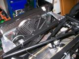
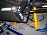
The radiator doesn't fit well to the brackets because there is either a gap at the top, or a gap at the bottom. I spoke to Mark at the factory about this, and he told me that they just put a spacer at the top. You can see this in the pictures, and where I had tightened the bolts it had bent the brackets out of shape.
I cut some 6mm tubing for the bolts to pass through at the top and then tightened it all up. The radiator seems much more secure, and also it has straightened out the brackets nicely now that all the surfaces sit flat (forgot to take a picture of the final result though).
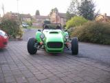
Fitting the cycle wings is a job that could wait, but since we've got a spare hour until we need to go out we decide to get it started.
They bolt to the front upright using 3 bolts, and then it's our job to fit the arches to the brackets. We decided it would be easiest to drill 4 holes in measured positions on each bracket, then move the wings into position, mark them from underneath, drill, and then hope they line up.
The metal is very tough and it takes a while to drill through all 8 holes (4 on each bracket). We put the wings into place and they immediately transform the look of the car, but we leave the fixing to another time since we need to get out for a friend's birthday.
Laurence
 |
 |
 |
 |
 |
I tried the handbrake the other day and it wasn't working. It would bite, but not nearly enough to stop the car from rolling down a hill for example. I had a look to see what was wrong, and the springs on the handbrake were not being moved hardly at all when the handbrake was applied.
I went back to check the manual, and I quickly spied a problem. The ends of the handbrake cable go over the hook on each calliper as already fitted, but then the cable must travel down through the round bracket beneath the lever, so that when the cable is pulled, the force has a completely vertical motion which will be translated into pulling the hook down and compressing the spring.
Easier said than done though as the cable is very tight. I slackened it right off at the top, which then made the job much easier. I removed each cable from the hook, poked it up through the bracket, and then put it back over the hook again.
Immediately I can see how much better it will work, and when I try the handbrake you can see the springs being compressed which didn't happen before. So I adjust the slack out of the cable and call it a night there. I don't want to start anything new tonight.
Laurence
 |
 |
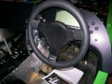
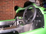
Tonight I fitted the steering wheel. There is a plastic collar, but it comes into contact with the dash so I have left it off.
It was just a case of spinning the wheel far left, far right, then going in-between the two. Any final adjustments can be made using the tracking rod.
The rubber cover comes off very easily - I'll probably have to use a light glue on it.
It's pub-o'clock...
Laurence
 |
We have loads of loose ends to tie up today. They are mostly little jobs, but they will all save time later down the line. The idea today is to get the majority finished, and then see if the car moves on the ground.
I left the cable tidying half completed, so I carried on with that so that it's all well clear of the prop shaft, and other moving parts. I also did what I could with the dash loom too. It's such a big clump of wiring it's hard to do much with it though, so perhaps this will need to be improved later down the line.
Whilst I did this, Matt and Jonny drilled some holes through the dash board and into the scuttle, and then bolted it into place. Jonny also discovered that I had fitted the dash switches wrongly, and so re-fitted and tightened them so they would stay put.
They then went on to fit the top panels for the transmission tunnel. We found that the reverse box and gear shift holes needed cutting slightly larger as the levers came into contact with the panel, so a bit of work with the Dremmel quickly solved that. They then used self threading screws to fix the front and rear panels down and into place.
Westfield have finally sent the lower nose cone bracket too. I was really surprised that only 2 bolts were used to secure the nose cone, but the bracket forms the third bolt, and holds it into place perfectly. There are two Rivnuts at the very front of the chassis to secure the bracket, and then you just drill and bolt the nose cone into place. We lined up the nose cone to the bonnet, and then when we were happy, I drilled.
With these bits complete, we fitted the body panels, and lowered the car to the floor. Wow it's low - this ride height is going to have to be altered quite a lot. We pushed the car out of the garage, started it up, and then saw if it would drive. I popped it into first, gave it a few revs and then...STALL! This clutch is awful - it has about 3mm if travel between fully engaged, and fully disengaged!
On the second try I used no revs and I was able to creep it into the garage. Although I had only driven 2 metres, I was absolutely delighted with the effort. The guys shared my happiness as they watched. This is a very good place to finish for the day.
Laurence
 |
 |
 |
 |
 |
 |
 |
 |
 |
 |
 |
 |
 |
 |
 |
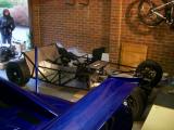
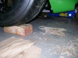
The car is so low to the floor that even the ultra low jack I have will not get under the front, so I had to jack the wishbones up and drop the car onto bricks, then get the jack under the front. After a lot of measuring and re-measuring, I set the front ride height to 110mm, and the rear to 130mm. The jack now fits under the front ok too :)
I am not to worried about it for now, as it will all be re-done when we have a proper cornerweighting session on the car. The car looks a lot more drive-able at it's current ride height than it did before.
Laurence
 |
 |
 |
 |
 |
 |
Now that the ride height was set, I decided that the wishbones could be tightened. Before this, I checked that both rear wheels were running about the right amount of camber and toe-in. I just made sure that the exposed threads on the rose-joints were the same on both sides.
It doesn't mean they will be ideal values, but it does mean they will be the same each side, so the car should be stable. There is no point wasting time on getting it right when the ride height is going to change, which means the other settings will too, and the geometry will have to be re-done anyway.
With this done, I torqued up the suspension and wishbone bolts at the rear, and then moved to the front.
The front camber and toe can be adjusted with the wishbones fully light, so I went ahead and torqued the front bolts too. Some of the bolts are difficult to get to, so I jacked the car up and they were easier to get to.
Once I had dropped the car back to the ground, the suspension was rock-solid. This is not right - I'll speak to Westfield on Monday...
Laurence
I spoke to Simon at the factory and he said that the wishbone bolts should ALWAYS be torqued with the car on the floor, so I went over each bolt, loosened it, jumped up and down on the car a few times to free the bushes, and then tightened them again. The car has a bounce now, so this had done the trick.
The only thing left to do is roughly set the camber of the front wheels, and then do the toe. I did this by eye, and played around with it until it looked right. I'll do it properly another time.
I did the final bits and pieces to prepare the car for its first outing. I was in a "do I, don't I" mood with it. I just needed to extend a cable for the oil pressure sensor, tighten the battery terminals, give the car a final once-over, and then that was it.
Matt had gone to the cinema, because I didn't think we would be driving the car that evening, so I gave my Dad a shout to come out with me.
We pushed it out of the garage and then back and forwards a few times to turn it around. I didn't fancy maneuvering it as the clutch is so sharp. My heart was pounding and I felt a bit sick. I wasn't really dreading it all, but it's just the when you've spent nearly 4 months of your life on something like this, it's more than just a drive.
I've never been nervous about driving a car. Not any of my old cars, not the Noble, not any friends cars, not on a trackday for the first time - never. This is different though. This is really different.
I jump in and so does my Dad. Harnesses on in case of any sudden jolts. I start the car - oil pressure is very stable at 4 bar, coolant is 16 degrees and rising, and the car seems a lot quieter outside. It was 9:45 so I didn't want it to be too loud.
My Mum was hanging out of the window watching. I ask my Dad if he's ready and he says yes, so "clonk", into first gear, a few revs, and...STALL!
This clutch is so tricky - try again. It's moving! I don't quite make the turn so I test out the reverse box. Back we go and it seems ok. Forward again, careful on the clutch and away we drive.
Up the hill and down the road. We don't have any front wheel arches (cycle wings) on, and stones are everywhere. It's like we're driving through gravel or something. I think that the tyres are so sticky that they just pick them up and throw them, whereas most cars would just run over them.
We drove about half a mile down my road and the next road. Although it's illegal, I didn't take the piss with it. We stayed to 25mph and the roads were all cul-de-sac roads so have extremely limited traffic. In addition, it was after 9pm so very few people about.
The engine warmed up very quickly and held at temperature. We turned round and drove home slowly. The brakes are virtually non-existent and will really need some bedding to work well.
We got back to the drive and cut the engine so we could push it back into the garage. Smoke was pouring out of the exhaust for ages after cutting, and smelt funny. I turned the engine back on, run it for a couple of seconds, and then turn off again. The smoke has stopped so it must have been the cat burning off oil and rubbish. Still worried me at the time though.
All in all very happy though - nothing fell off, so I'll go over everything with a spanner tonight and make sure nothing has worked loose.
It took me over an hour before I could eat as I was so excited still. It was such a wierd feeling.
Laurence
Matt came home last night and was pretty gutted that he missed the first outing, so decided he would drive it this evening instead.
He came home from work around 5:30, and we got the car straight out. It was beautiful weather, and Matt just couldn't wait to get in the car. We pushed it out of the garage, started it up, jumped in, and away we went.
We took the same route as before - sticking to only our road and the next which are both dead end roads, and see very limited traffic.
I warned Matt about the clutch, but immediately he stalled a few times. We found that the best thing to do is pull away with no throttle, which stops the clutch from snatching the revs and stalling.
Matt got the car going, then stalled again at the end of our road and blocked a car behind us as he wasn't sure if he was in neutral to start the engine again. We waved the car on, and then continued up the hill.
We got to the top of the hill, turned it round, and then started filming:
http://www.youtube.com/watch?v=_Kk900AzCnQ
We got the car back, checked a couple of things, and then I decided that I wanted a go too - I just couldn't resist it. I went back and did the short route that Matt just did.
Here is the video: http://www.youtube.com/watch?v=XwDIYUFY13I
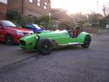
Matt wanted to get a couple of pictures of the car, so we took a couple and then Matt went out once more in the car. Whilst he was driving I noticed the DASH2 giving a engine temperature readout of 120c! I panicked and told Matt to get the car back to the garage as quick as possible and then turn off the engine.
Strangely enough, the cooling fan was turning on and off as it should do, and the fan is controlled by a thermostatic switch which opens at about 90c, so I must have wrongly configured the DASH2. I'll go over my settings and check.
Laurence
 |
 |
 |
 |
 |
 |
We haven't really done a great deal on the Busa for a few days, but I have been playing around with a fuel leak. Each time we walk into the garage there is a strong smell of fuel, and I spied where it was coming from earlier in the week.
I thought it was the hose that goes from the fuel tank outlet to the fuel pump, but instead it turned out to be the boss that threads into the tank. I had drained the tank and checked it out earlier in the week, and there was no O-ring fitted when it was assembled at the factory. I fitted on myself, but it's still leaking so Westfield asked for the tank back for examination.
It's not to difficult, but you do get very smelly when draining the tank as fuel gets everywhere. Once drained I removed the tank and looked at the boss and it will not go any tighter, so Westfield can have a look at it.
Laurence
 |
 |
 |
The new fuel tank arrived from Westfield today. The old one was leaking around the boss insert at the bottom of the tank in the swirl-pot-like section. I had already checked it to see if it was assembled correctly and the O ring was missing.
Even after adding one, it still leaked and when I tightened it it would no longer un-tighten. It was something that should have left the factory correctly so they agreed to send a new tank
After speaking with Gavin, apparently this boss should leave the factory with the thread covered in copper grease so the aluminium does not bind, and my next door neighbour had said that the reason that the boss would not come out was for the same reason a few days previous. Anyway, it's not a concern now since the new tank is here and there looks like there is plenty of copper grease on the thread.
I didn't trust the readings I was getting before from the tank level sender, so I decided to remove the fuel tank sender and check first of all, the resistance at full and empty by manually moving the arm, and secondly, the arm range of movement to ensure accuracy.
The VDO sender gives 3 ohms when empty, and 180 ohms when full. This gives me everything I need to scale the Dash2. I made a slight alteration to the arm length, and then re-assembled the tank.
I'm a bit of a pro at getting the tank in and out of the car now having done it on more than one occasion, so it didn't take me very long to put it back in the car and have it ready.
Laurence
 |
 |
Now that the SVA and other bits are out of the way, and the car has a few drives under its belt, one thing that's pretty clear is that the clutch feel is terrible. When you are rushed to pull away, 9 times out of 10 you will stall.
The problem is not so much that the clutch pedal is very light (which is is), it's more that the pedal has literally a few mm of travel between fully disengaged, and fully engaged. Slipping it to pull away is near impossible.
I had read about a clutch pedal modification on the WSCC, so I read up on it again - here is the thread: http://boardroom.wscc.co.uk/cgi-bin/ikonboard.cgi?act=ST;f=12;t=38381
So basically what is needed is to move the point at which the clutch rod connects to the pedal to a point nearer the pivot. Effectively, if the pivot point and the point where the rod attaches to the pedal is 100mm apart, and you reduce this to 50mm, you will double the distance required for your foot to engage and disengage the clutch.
Sounds easy, so let's have a go...
I marked the pedal at the lowest point I could place the hole, and then removed the pedal. I then drilled hole and then popped the pedal back into place.
Well the modification has done exactly what it should, but the pedal feels much lighter too and I'm not sure if I like it. A lot of this was down to the fact I hadn't re-set the pedal stop and the rose-joints in the clutch master cylinder. It was the dead travel at the top of the pedal where you are just taking up slack that made the pedal feel bad.
Once I had re-adjusted the master cylinder settings the sloppiness had gone, and the clutch is now much easier to modulate in traffic etc. All in all a successful job.
I just need to find a way to firm up the pedal a little now, as it feels a little too light for my liking.
Laurence
 |
 |
 |