Wednesday is normally a night when Matt and I go out with our mates for a beer and a catch-up, but it has become an unofficial car night. It's ok though because the mates we would normally meet come round to help us instead of drinking beer, so we're not social outcasts after all.
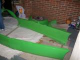
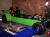
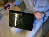
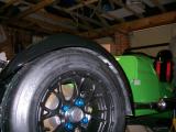
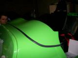
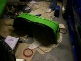
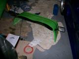
Kriss was looking forward to the body preparation and really wanted to be involved, so he and Jonny got round about 7:30pm and we started work. We went and got the main body panel from the greenhouse where it had sat under covers since collection, and Matt retrieved the rear arches from the loft. We moved the Noble, and sat the bodywork down in a nice big space next to the car on a blanket for protection.
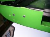
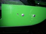
We rubbed the arch locating blocks down removing any rough edges to ensure a flush fit, and then Jonny and I set about bolting the arches to the main body section. We G-clamped each arch in 3 places, then marked the 10 holes we were going to drill. It quite weird, but the drill literally gets pulled through the plastic once the hole is drilled, and you really have to be ready for it!
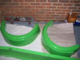
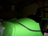
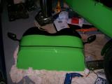
Whilst we were doing this, Matt and Kriss removed the manifold from the engine so the body panel could sit in place once all of the preparation had been done. It didn't take long before both arches were firmly fitted to the body. The fit is generally good, although the gaps at the bottom of the arches is a little bigger than the rest. Nothing to worry about though.
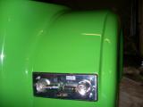
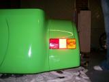
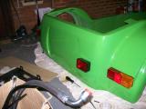
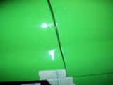
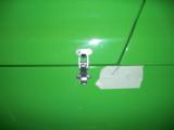
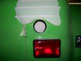
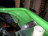
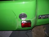
Now the rear lights could be fitted to the body - indicators pointing outwards. I was glad Kriss was here for this, because he has a good eye for lining things up, and although the lights already have mounting points, there is still plenty of room to get things wrong, and once you have drilled...
We decided on a final location, then removed the light and drilled a hole in the centre for the wires to route through. We then held the light back in position and drilled the 4 holes using the bracket as a template - this way the 4 holes will ALWAYS line up (even if they are not straight).
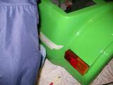
The lights look good, so we secure the brackets into place (using a p-clip on one bolt to secure the wires) and then fit the light cover. The lights look terrible as units, and we might well upgrade them to the rounded type. They fit nicely though.
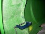
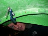
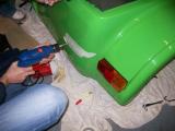
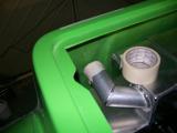
Now the fog light can be fitted, but it has no actual mounting point, so we have to be very careful with its position. It looks really easy, but we were very careful with the measurements and the whole process took most of the night.
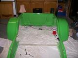
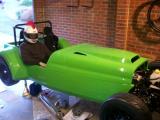
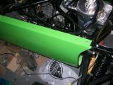
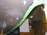
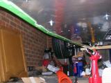
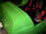
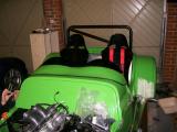
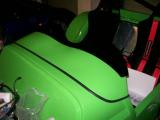
Jonny and Kriss were a big help with it, and as a last team effort before they have to leave, we picked up the body and placed it onto the chassis, stand back, and admire! The colour looks fantastic, and so does the car. We stop for a bit, feeling very happy with our achievements so far.
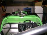
Matt and I carried on for a bit, and made sure the body was correctly aligned. We then looked at the roll-bar but decided it was pointless fitting it as we already had the mounting points for the RAC roll bar, so we just put it back down and decided we'd order the RAC the next day. A great night's work on the car which left all of us feeling very happy.
Laurence
 |
 |
 |
 |
 |
 |
 |
 |
 |
 |
 |
 |
 |
 |
 |
 |
 |
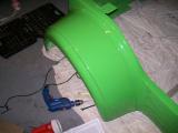
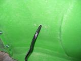
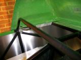
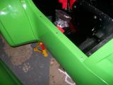
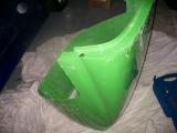
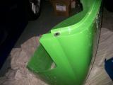
You know when you put off a job for as long as possible, and keep trying to find other things to do? Well eventually you run out of other things to do, and you have to tackle the job you were putting off. In this case, it was cutting a hole in the main body panel for the exhaust manifold to pass though. GULP!
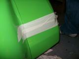
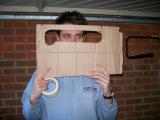
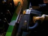
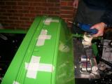
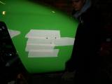
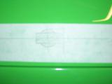
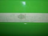
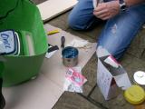
So how do you tackle it? You get your friend Kriss round, who is good at things like this. We looked at it for a while, and Kriss decided that the best thing to do was to make a cardboard mock-up. He marked up a rough shape in the cardboard using a ruler and a compass so we had straight edges and perfect curves, and then adjusted his template a couple of times. Eventually we were left with a nice shape (pictured) which we transferred to the body using masking tape.
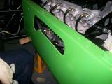
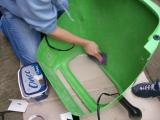
We decided that the best way to cut the hole was using a jigsaw with a very thin blade to make the curves easy to cut, and I was nominated to do the cutting since I was the only one who had really used it before. I was really worried about it, but once we got started the jigsaw really made it easy. The jigsaw works best on higher speeds against the body plastic since it is much less likely to "catch" and damage the body.
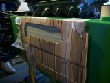
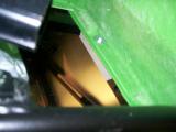
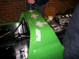
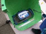
We stopped to examine the cut after the first line and it was almost perfectly straight. I tackled the first curve and again, the jigsaw took it really well. After just a couple of minutes we had a really nice shaped hole. We dusted off and had a trial fit.
The left side of the cut needed enlarging a little as it was too close, so we drew a couple more cutting lines and started with the jigsaw again. The 2nd cut was perfect and the manifold went in really nicely, leaving enough clearance around the manifold, but not so much that it looks untidy.
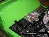
We were all very happy with the work, and Kriss' template made it very, very easy. We decided to remove the manifold now until the body was fixed into position.
With this done we thought we would have a trial fit of the other body panels. The removable scuttle panel will need some cutting in order to fit nicely. Kriss had a quick look at this, and then left it to Matt to finish. Also, the scuttle itself will need some cutting as it fouls the steering column, and also the wiring loom grommets. This doesn't take long though.
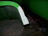
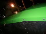
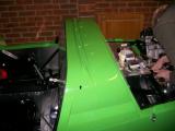
Now for the body fixing. The rear of the bodywork needed fixing into place, and it is done using 2 large rivets each side. The rear of the car looked wonky though, and no amount of moving it would help. Eventually we realised that if both sides were riveted then it would have to sit straight...hopefully!
Out came the drill and we fixed each side down. The rivets move the rear of the body up about an inch, and this sorts out the alignment perfectly. The rear now sits perfectly straight.
The next thing we'll have to do is fix the other body panels into place, but there will be a lit of measuring and checking, so it's probably best to make a fresh start on this, and besides, we're heading out for the evening, so we get cleaned up and out comes the beer. Well done guys.
Laurence
 |
 |
 |
 |
 |
 |
 |
 |
 |
 |
We left the panels fitted into place, but not fixed down with the exception of the rear section. Before we could fix any more of the body down, the other body sections must be fitted into place and fixed one by one, re-checking alignment at every stage.
This involves lots of marking. There are several rivnuts already inserted into the chassis, and you must transfer each of their positions onto the body panels, and then drill them. Accuracy is important here as you don't want to make the holes too big!
The manual says there are 6 rivnuts for the scuttle and 2 for the nose cone, but there are in fact only 4 for the scuttle.
I marked in several places on the body using marking tape and a pen, and then removed everything except the scuttle. I then drilled 3 holes per side on the bodywork and then riveted the top of the main bodywork section into the top chassis rail along the engine bay area. The rivets are very long and each take 2 goes with the riveter.
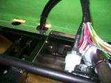
Now the scuttle can be fixed down with the holes I had drilled, and bolted down into the rivnuts in the chassis using some large washers. Before it would fit neatly I had to make a couple of modifications to the scuttle. We previously cut a hole to allow the steering column to pass through, but the two wiring loom grommets were also causing problems, so out came the jigsaw.
The holes are very difficult to cut as the cuts need to be made right on the edge of the angle, but I managed it. I'll neaten them up later as the scuttle is easily removed.
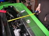
Now the main body section between the scuttle and the rear arches could be secured down, again, using 3 rivets per side. I quick check with the tape measure that everything still lines up, so I move onto the bonnet and nose cone.
The bonnet is actually secured into the nose cone using pegs which insert into the nose cone to stop the bonnet from lifting, but it still make it easily removable. In order to achieve this you have to drill holes in the hidden edges of both. The measurements must be spot on with both panels here - they must line up perfectly.
I marked and drilled the bonnet, then G-clamped the bonnet and nose cone together - adjusting a couple of times until I was completely happy with the alignment. This is a two person job, so my Dad helped. Matt was on Call Of Duty 4 and once he starts he doesn't stop, so I had written off the idea of help from him tonight!
There was enough room to drill through the nose cone using the bonnet as a template, so my holes lined up perfectly. With the panels separated I enlarged the bonnet hole as instructed, and then enlarged the nose cone hole to 19mm (I didn't have an 18mm cutter). 19mm turned out to be perfect for the grommet though - 18mm would have been to tight, so I got lucky. I then secured the pegs into the bonnet and gave them a trial fit.
All looks good, but the nose cone seems to flop forward as soon as you don't support it, which creates a big gap between the bonnet and nose cone. I wonder if this will get any better with both items secured down?
Laurence
 |
 |
 |
 |
 |
 |
 |
 |
 |
 |
 |
I came into the garage not really looking forward to tonight's work because I knew how much trouble I was having making the nose cone line up. Kriss and Jonny were round tonight to help too, so hopefully we might be able to work it out.
I slotted the holes in the nose so it could slide around quite a bit until fastened. Once we've reached a sensible position I'll fibreglass over the large slots to tighten the holes up again.
We line the nose cone up with the bonnet and everything looks perfect, until I let go of the bonnet and it flops forward again. It's only fixed down by the two top rivnuts and there is no room for anything at the bottom, so I made up some spacers out of aluminium which sit next to the rivnuts to support the nose cone return edges a bit. It's better, but still not perfect - I'll speak to Westfield about it as it doesn't look right to me, and only 2 fixing points seems very inadequate for an entire nose cone.
Anyway, it's all lined up, so we can move forward with the fixing. The bonnet catches are next. We fit the hooks to the bonnet, then the catches to the body work. The best thing to do is fit the catch below its final closed position - this way the catch will be under tension when fixed. The first one wasn't fitted using this method, so I'll alter the hook slightly, either by bending it up a millimetre, or fixing something inside it to space it.
Now the bonnet catch arrangements are fitted we can finish the rest of the body fixing. The top side is finished, but the bottom side is totally loose. The bodywork needs holding tight to the chassis, so Jonny drilled the holes underneath whilst I held the bodywork in. We drilled the holes one by one, but upon riveting we found they didn't line up perfectly and had to open some of the holes ever so slightly due to the flex in the panel.
The best method is to drill a couple of holes at a time, rivet them, and then move onto the next two. The 2nd side was much easier as we adopted this method. Jonny got a tonne of body plastic in his eye and it went really red where he was rubbing it. Hopefully it won't have done any damage though. On a plus note, the body work is totally fixed into place now :)
Laurence
 |
 |
 |
 |
 |
 |
 |
I spoke to David at Westfield, who although is the parts guy, he knows almost as much as the technical guys. I told him about the nose cone flopping forward, and apparently there is a bracket which fixes underneath too. There are two rivnuts in the very front of the chassis cross bar, but the aluminium floor pan covers them up. You fix the bracket here, and then secure it to the nose cone. The only problem is that we don't have that bracket, so David is sending one out with the next batch of parts.
So we are currently still waiting on:
- Lower nose cone bracket.
- Engine mounting bolts (only just discovered).
- Speedo transducer (missing from kit - normally supplied with dials, but we're using the digi dash so I can see where the error has crept in).
- Water temp sender (same problem as speedo transducer).
- Oil temperature sender (purchased recently).
- Oil pressure sender (purchased recently).
- Hinges to mount the ECU tray under the scuttle.
- Our modified ECU loom and fuel rail segment. These have been with the electrician for about 6 weeks now and they can't get hold of him, so I'm starting to wonder if it's been lost!
Laurence
Once again, we find ourselves faced with a task that has no instructions. We'll have to see how we get on. Kriss and Jonny are round to help Matt and I.
Looking at the aeroscreen, there are 5 studs which secure into the scuttle, but where? We think we have worked it out, so we mark our points and off we go. The first fit is well off - the holes will all need slotting. The marking is correct, but the side studs can't fit in until the top studs are in, but they can't fit in because the side studs are in the way - you'll see what I mean when you have to fit one!
So we slot the holes a bit, and although the screen fits, it still doesn't look right, and there is little support against wind. I'll have to ring Westfield when they are open.
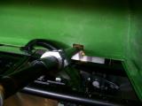
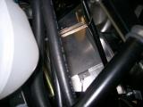
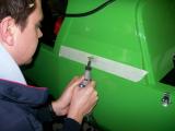
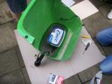
I did however manage to fit the battery tray. The tray goes right at the front of the car, and fits in with the narrowest of margins between the oil tank, the steering rack, and the crossbar.
I drilled the strap holes down through the chassis, bolted it down temporarily, checked the battery could be removed, and then when I was happy I measured my points and drilled up through the floor pan.
Each of my holes were perfect, so I riveted the tray down and called it a day.
Laurence
 |
 |
 |
 |
 |
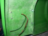
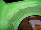
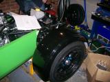
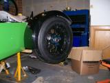
We have already drilled the holes into the cycle wing brackets, so now all we need to do is position the arches into place, mark them, and then drill through, leaving a hole that we can bolt through.
We followed the manual's guidelines for positioning and then marked onto the arch from the underside using the holes we had drilled in the bracket as a template.
Now we just drilled through and then bolted the M5 screws down. The only problem is that we are out of foam tape which should be fitted between the bracket and the arch, so we fit them loosely until we can get some more.
Laurence
 |
 |
 |
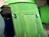
This job was probably as scary as the exhaust manifold cutting, and a job that would ruin the same large section of bodywork if I got it wrong.
I started by taping up the fuel filler neck on the tank, as the last thing you want is a load of body dust clogging up your fuel filter and injectors.
I then covered the entire area that the hole would be cut in with masking tape, and then started marking. The way I decided to do it was to mark a cross INSIDE the bodywork which was the exact centre of the tank's filler neck. I then drilled a small hole through the centre from the inside. Now, when looking from outside you have a centre mark, so I set up my hole saw, drilled through with the drill bit, checked it was central on the inside, and then made contact with the hole cutter.
The hole is absolutely spot on and I'm absolutely delighted. That is until a few minutes later when I realise that the tank wasn't central when I drilled the hole! I break into panic thinking I've wrecked the hole thing, because there is no way the lower roll bar bolt will go in on the right hand side as the tank is too close.
There is actually a lot of room for maneuver with the hole though, so I made it larger on the left hand side, which allows the whole tank to shift over too, and the roll bar bolt fits as it should.
I was very lucky and really should have checked that the tank was central again before cutting, but it's just one of those things! Still, I got away with it...just!
All that's left is to connect the rubber hose to the tank, and then connect it to the fuel cap, but it's impossible to get the rubber hose over the tank filler neck without removing the tank, so I would advise you fit the rubber hose when you fit the tank. I had to remove the entire thing including all fuel lines to get mine on!
Once this is done it's all very simple - the hose needs clamping onto the tank and onto the fuel cap, and then the cap can be bolted down using the supplied fixings.
Laurence
 |
 |
 |
 |
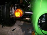
Whilst we are STILL waiting for a fuel rail and a few other assorted parts which prevent us from starting the engine, we decided to fit the indicators into place. This is another job that will build up and cost time at the end of the project, so it's good to tick these off the list now.
Kriss and I marked up the nose cone using the exact measurements as documented in the manual. We used a spirit level to make sure they were straight though, and then measured the holes both sides to ensure they were symmetrical.
Once happy we drilled through the marked holes.
Kriss left me to bolt the indicator pods into place and wire them whilst he and Matt carried out some major work on the aeroscreen (more on that later).
I fed the indicator wires through the holes and bolted the indicator pods into place. Now the lights just had to be fitted into the pods. It was quite tricky though as the holes in the pods don't quite line up with the holes in the lights.
The trick was to fit rivets into 2 of the holes, then force the whole unit over with about a 1cm gap between the light and the pod. Once all 3 rivets were aligned then they just needed fastening with the riveter, and then I made up block terminals for each side.
Our aeroscreen was very wrong, so Matt and Kriss made some adjustments. There really is nothing I can say about fitting the screen - it's purely trial and error. Don't worry about slotting the holes because the washers you fit are large enough to compensate.
We eventually reached a position which we liked, so we bolted it down, and then riveted the central bracket into place. We had to shorten the bracket slightly, but it fits really nicely now. Matt and Kriss finished it off with some black edge trim, and I'm so impressed with how it looks.
A sterling job by both Kriss and Matt.
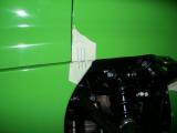
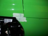
Now the side repeaters. The Westfield manual says to fit them on the body, but every car I have seen has them on the scuttle. I believe the measurements were 50mm from the bottom and 150mm from the front.
Kriss drew out the shape in the manual onto the scuttle using masking tape, and then out came the Dremmel. We broke a few blades, but a really neat hole was cut and the side repeater fits very tightly, so we did the same for the other side and called it a night there.
We forgot to take a final picture with the repeaters fitted, but believe me they look great.
Laurence
 |
 |
 |
 |
 |
 |
 |
 |
 |
 |
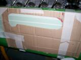
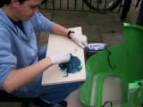
Kriss popped over this morning and had picked up some fibreglass resin from Halfords on his way to fix the mesh into the nosecone.
The kit is actually very easy to use - you just mix the resin with a bit of hardener and then smear it on. Kriss thought it best to fill the gap underneath the mesh first so the mesh had something to sit on, but in actual fact this is not needed at all.
The stuff is so viscous that you could just smear it over the top and it would hold just fine. It has added a couple of KG to the weight of the nosecone though, so I would do it much thinner next time. However, the mesh is rock-solid, and it's another job off the list.
Laurence
 |
 |
 |
 |
 |
The mirrors are horrible looking units, but we'll just get through the SVA with them and then upgrade to something else - probably carbon.
Anyway, we removed the scuttle and then bolted the mirrors into place.
Laurence
 |
 |
 |