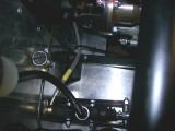
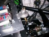
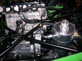
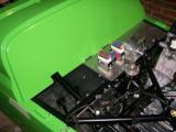
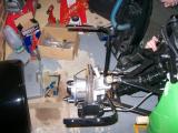
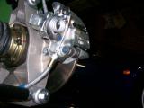
Tonight Matt and I had a few loose ends to tackle. Connecting the engine output flange to the prop shaft, fitting the radiator expansion tank (header tank), fitting the dry sump oil tank, and fitting the fuel pressure regulator.
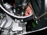
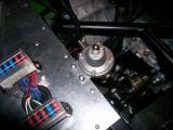
The first task is definitely a 2 person job. I laid on the floor with the torque wrench whilst Matt held a spanner on the other end of the bolts. We tightened them all, and then one by one we loosened a nut and bolt, applied thread lock, then re-tightened and torqued them. To stop the prop spinning we put the engine in gear each time to lock it. Once all 4 were tightened we marked each one so we could check for movement over time.
Whilst we were there we fixed the clutch line onto the slave cylinder.
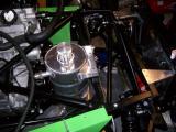
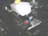
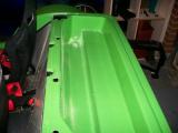
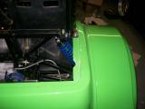
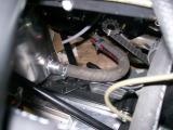
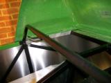
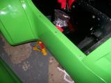
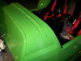
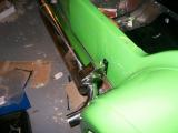
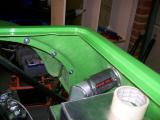
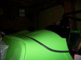
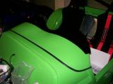
The oil tank fits really nicely. It has a right angle bracket at the bottom which fits perfectly over the frame rail at the bottom and it holds really well. Now you just hold it straight and drill through the top bracket and then all the way through the chassis rail. With this done you can just bolt it down with some M6 bolts and washers. We moved it as far over to the offside wheel as we could to allow room for the battery tray. The tank bracket covers the last letter of the chassis number etched into the frame rail. Hopefully this is not an issue though as the number is duplicated on the identification plaque.
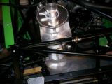
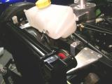
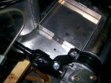
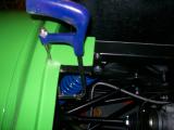
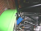
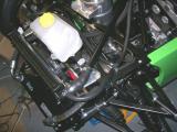
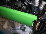
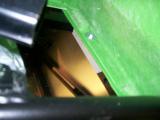
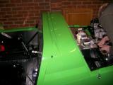
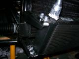
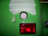
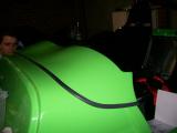
Now for a job I had looked at several times and just given up on - the expansion tank. Simon from the factory had send me some pictures to help me out. The fat tube points to the rear of the car, and the header tank fits on using the two plastic mounting brackets on the tank itself. It bolts to the same chassis rail that the horn is fitted to.
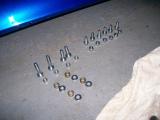
The flat bracket bolts to the rail so you just drill straight through both sides and fix into place. The second bracket comes off at a 45 degree angle to the car, so you have to mount it to the chassis using the supplied black bracket. It fixes underneath the chassis rail, and then you bolt it to the 45 degree bracket coming off the tank. This now feels nice and secure.
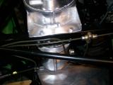
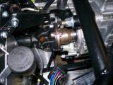
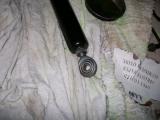
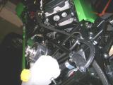
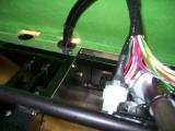
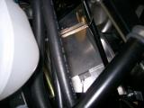
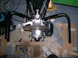
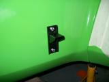
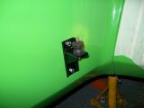
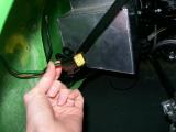
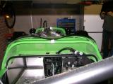
The fuel pressure regulator is another item which is left completely out of the manual, but it fixes to the chassis bulkhead rail. There were a few options for fitting, but I chose to use self tapping screws and locking washers as they were supplied with the kit.
The inlet sat very close to the gear change quadrant, but by the look of the unit, the inlet can be on either side, so I removed it and fitted it to the other side and swapped the blanking plug over too. These were on very tight and there was evidence of some thread seal, so I used thread seal when re-fitting both the nipple and the blanking plug.
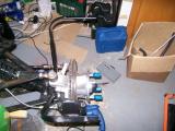
I looked at the battery tray, drilled a couple of holes, and then realised that the tray's securing strap was missing, so I called it a night there.
Laurence
 |
 |
 |
 |
 |
 |
 |
 |
 |
 |
 |
Tonight Matt and I both had the evening to work on the car. I wanted to get the coolant plumbing done, and Matt wanted to get the roll bar fitted, so we worked at opposite ends of the car and helped each other when required.
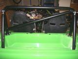
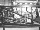
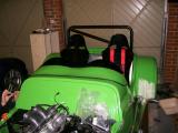
The main bodywork section has a square tab which sits on top of the standard roll bar mounting points, but the RAC bar bolts directly onto the supports, so we cut the tabs off. The boot box requires cutting into as the support bars for the roll bar pass through it, so it's just a case of trial and error with the marking and cutting.
Before this could be done, Matt has to cut some holes into the boot box so that the top harness eye bolts could sit into place. He measured where these needed to go and then cut them with a hole saw. They were almost perfect first time and the harness bolts sit really nicely in place. We'll need to get some grommets for the spacers to tidy up the holes eventually though.
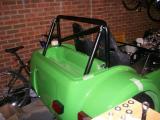
Now we bolted the roll bar into place. You get a giant bag of nuts, bolts, and washers, and you need to use the 6 shortest Allen head bolts, 6 washers, and 6 nylock nuts to secure the main section of the roll bar into place. One of the bolts is difficult to get into place as the cross bar is very close to it, so we used an Allen key bit and a spanner - a rachet was far too tall.
Now we held the support bars into place and marked where the bars touched the bodywork as these sections needed to be cut slightly. They don't need to be too neat though as the boot box will cover them.
Now for the hardest bit - cutting the holes into the boot box itself. This is really difficult as you have to cut through corners at an angle. We fitted the bars into place, made some marks and measurements of where the bars started and finished, and translated these marks into the boot box which described a line to cut. Matt did very well with the hacksaw. The lines are not that neat and will definitely need smoothing and finishing, but I was very impressed overall. He stuck with it well, and the roll cage looks awesome!
Whilst all this was going on, I was sorting out all of the coolant hoses. Westfield supply some hard pipes, and some rubber hoses too, and I had to get some images sent to help me out. All of the images I took have come out really dark. I have lightened them in Photoshop so hopefully they will be clear enough.
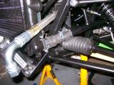
The two rubber hoses have a bulge at one end and and reduce down. The bulges fit on the radiator connections and then onto the solid pipes. You cut these pipes to length and then use the other half on the opposite end of each of the solid pipes to connect to the engine.
The top radiator connection goes to the slightly angled hard pipe, and then connects to the thermostat. The bottom connection goes into the 90 degree hard-pipe, which then curves right round the back of the engine near where your fuel pipes terminate on the passenger bulkhead. From here you use the rest of the rubber hose which you cut and connect it to the engine (very near the water pump). I couldn't get any pictures of this, but Westfield have some which I attached.
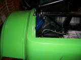
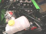
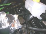
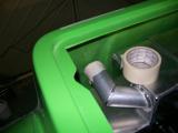
There is also a lot of plumbing to do with the header tank. The large outlet which points to the oil tank connects to the lower hard pipe using the supplied rubber pipe. If they seem tight, stick them in boiling water to make them a lot more flexible and they fit really easily. You need to cut this pipe to length and then push it over the stub on the lower pipe (pictured).
There is a final outlet on the header tank which points to the offside front wheel. You need to cut some rubber pipe (I used fuel hose which is what was used in Westfield's pictures). This pipe goes from the outlet to a T-piece. This T-piece then needs 2 further pipes coming off it. The first connects to the top of the thermostat (just above where the first hard pipe finishes). The last t-piece connection goes to the very small outlet from the radiator. There are pictures to show all of this.
Now with this done, I turned my attention to the oil pipes. The oil cooler pipes are very easy to fit - one goes to the oil tank return, and the other goes to the scavenge pump. The last pipe is one you must cut to length and it connects the oil tank outlet to the engine sump. That's most of the plumbing done. I'll cable tie it all up tight when the engine has been started and we're happy it's all as it should be.
Laurence
 |
 |
 |
 |
 |
 |
 |
 |
 |
 |
 |
 |
 |
 |
 |
 |
 |
 |
 |
 |
 |
 |
 |
 |
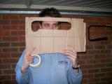
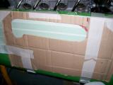
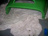
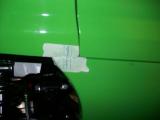
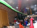
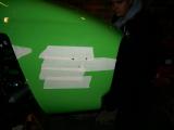
You know when you put off a job for as long as possible, and keep trying to find other things to do? Well eventually you run out of other things to do, and you have to tackle the job you were putting off. In this case, it was cutting a hole in the main body panel for the exhaust manifold to pass though. GULP!
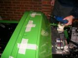
So how do you tackle it? You get your friend Kriss round, who is good at things like this. We looked at it for a while, and Kriss decided that the best thing to do was to make a cardboard mock-up. He marked up a rough shape in the cardboard using a ruler and a compass so we had straight edges and perfect curves, and then adjusted his template a couple of times. Eventually we were left with a nice shape (pictured) which we transferred to the body using masking tape.
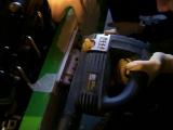
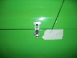
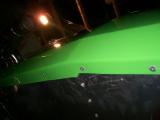
We decided that the best way to cut the hole was using a jigsaw with a very thin blade to make the curves easy to cut, and I was nominated to do the cutting since I was the only one who had really used it before. I was really worried about it, but once we got started the jigsaw really made it easy. The jigsaw works best on higher speeds against the body plastic since it is much less likely to "catch" and damage the body.
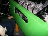
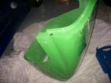
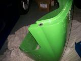
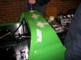
We stopped to examine the cut after the first line and it was almost perfectly straight. I tackled the first curve and again, the jigsaw took it really well. After just a couple of minutes we had a really nice shaped hole. We dusted off and had a trial fit.
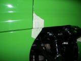
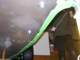
The left side of the cut needed enlarging a little as it was too close, so we drew a couple more cutting lines and started with the jigsaw again. The 2nd cut was perfect and the manifold went in really nicely, leaving enough clearance around the manifold, but not so much that it looks untidy.
We were all very happy with the work, and Kriss' template made it very, very easy. We decided to remove the manifold now until the body was fixed into position.
With this done we thought we would have a trial fit of the other body panels. The removable scuttle panel will need some cutting in order to fit nicely. Kriss had a quick look at this, and then left it to Matt to finish. Also, the scuttle itself will need some cutting as it fouls the steering column, and also the wiring loom grommets. This doesn't take long though.
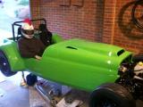
Now for the body fixing. The rear of the bodywork needed fixing into place, and it is done using 2 large rivets each side. The rear of the car looked wonky though, and no amount of moving it would help. Eventually we realised that if both sides were riveted then it would have to sit straight...hopefully!
Out came the drill and we fixed each side down. The rivets move the rear of the body up about an inch, and this sorts out the alignment perfectly. The rear now sits perfectly straight.
The next thing we'll have to do is fix the other body panels into place, but there will be a lit of measuring and checking, so it's probably best to make a fresh start on this, and besides, we're heading out for the evening, so we get cleaned up and out comes the beer. Well done guys.
Laurence
 |
 |
 |
 |
 |
 |
 |
 |
 |
 |
Just a small update on the engine side of things as we've had a busy day on the bodywork. The metal radiator pipes need securing using P-clips, but they sit too low if you fix them to the body, so you need to make up some spacers.
B&Q sell 6mm (M6) aluminium tubing for next to nothing, so I just cut some of this to length, drilled through the chassis rail, and bolted it down. It makes the pipe sit perfectly, and this is what the factory tend to do with their cars too.
I need to make an even longer spacer for the lower pipe, but I don't have a bolt long enough so I'll leave that for another day.
Laurence
 |
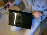
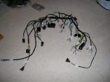
Apart from wiring the fuel pump into the loom, and running the main Westfield wiring loom in the chassis right at the beginning, I have not even thought about the electrical side of things. It's cold outside and I don't really fancy going out into the garage, so I decided to have a look at the dashboard loom and get my head around it indoors.
In the bag is a block connector kit, a few rocker switches, some toggle switches, and some warning lights. The warning lights will not be used though since we are using a digital dash which has inbuilt warning lights.
The digital dash unit comes with an adaption harness which must be connected to the standard dashboard loom. It all seems to make sense, but I can't understand how the rocker switches connect to the loom. I can't see anywhere for them to fit. I'll just put it all back in the bag and ring Westfield.
Laurence
 |
 |
 |
We left the panels fitted into place, but not fixed down with the exception of the rear section. Before we could fix any more of the body down, the other body sections must be fitted into place and fixed one by one, re-checking alignment at every stage.
This involves lots of marking. There are several rivnuts already inserted into the chassis, and you must transfer each of their positions onto the body panels, and then drill them. Accuracy is important here as you don't want to make the holes too big!
The manual says there are 6 rivnuts for the scuttle and 2 for the nose cone, but there are in fact only 4 for the scuttle.
I marked in several places on the body using marking tape and a pen, and then removed everything except the scuttle. I then drilled 3 holes per side on the bodywork and then riveted the top of the main bodywork section into the top chassis rail along the engine bay area. The rivets are very long and each take 2 goes with the riveter.
Now the scuttle can be fixed down with the holes I had drilled, and bolted down into the rivnuts in the chassis using some large washers. Before it would fit neatly I had to make a couple of modifications to the scuttle. We previously cut a hole to allow the steering column to pass through, but the two wiring loom grommets were also causing problems, so out came the jigsaw.
The holes are very difficult to cut as the cuts need to be made right on the edge of the angle, but I managed it. I'll neaten them up later as the scuttle is easily removed.
Now the main body section between the scuttle and the rear arches could be secured down, again, using 3 rivets per side. I quick check with the tape measure that everything still lines up, so I move onto the bonnet and nose cone.
The bonnet is actually secured into the nose cone using pegs which insert into the nose cone to stop the bonnet from lifting, but it still make it easily removable. In order to achieve this you have to drill holes in the hidden edges of both. The measurements must be spot on with both panels here - they must line up perfectly.
I marked and drilled the bonnet, then G-clamped the bonnet and nose cone together - adjusting a couple of times until I was completely happy with the alignment. This is a two person job, so my Dad helped. Matt was on Call Of Duty 4 and once he starts he doesn't stop, so I had written off the idea of help from him tonight!
There was enough room to drill through the nose cone using the bonnet as a template, so my holes lined up perfectly. With the panels separated I enlarged the bonnet hole as instructed, and then enlarged the nose cone hole to 19mm (I didn't have an 18mm cutter). 19mm turned out to be perfect for the grommet though - 18mm would have been to tight, so I got lucky. I then secured the pegs into the bonnet and gave them a trial fit.
All looks good, but the nose cone seems to flop forward as soon as you don't support it, which creates a big gap between the bonnet and nose cone. I wonder if this will get any better with both items secured down?
Laurence
 |
 |
 |
 |
 |
 |
 |
 |
 |
 |
 |
I came into the garage not really looking forward to tonight's work because I knew how much trouble I was having making the nose cone line up. Kriss and Jonny were round tonight to help too, so hopefully we might be able to work it out.
I slotted the holes in the nose so it could slide around quite a bit until fastened. Once we've reached a sensible position I'll fibreglass over the large slots to tighten the holes up again.
We line the nose cone up with the bonnet and everything looks perfect, until I let go of the bonnet and it flops forward again. It's only fixed down by the two top rivnuts and there is no room for anything at the bottom, so I made up some spacers out of aluminium which sit next to the rivnuts to support the nose cone return edges a bit. It's better, but still not perfect - I'll speak to Westfield about it as it doesn't look right to me, and only 2 fixing points seems very inadequate for an entire nose cone.
Anyway, it's all lined up, so we can move forward with the fixing. The bonnet catches are next. We fit the hooks to the bonnet, then the catches to the body work. The best thing to do is fit the catch below its final closed position - this way the catch will be under tension when fixed. The first one wasn't fitted using this method, so I'll alter the hook slightly, either by bending it up a millimetre, or fixing something inside it to space it.
Now the bonnet catch arrangements are fitted we can finish the rest of the body fixing. The top side is finished, but the bottom side is totally loose. The bodywork needs holding tight to the chassis, so Jonny drilled the holes underneath whilst I held the bodywork in. We drilled the holes one by one, but upon riveting we found they didn't line up perfectly and had to open some of the holes ever so slightly due to the flex in the panel.
The best method is to drill a couple of holes at a time, rivet them, and then move onto the next two. The 2nd side was much easier as we adopted this method. Jonny got a tonne of body plastic in his eye and it went really red where he was rubbing it. Hopefully it won't have done any damage though. On a plus note, the body work is totally fixed into place now :)
Laurence
 |
 |
 |
 |
 |
 |
 |
I spoke to David at Westfield, who although is the parts guy, he knows almost as much as the technical guys. I told him about the nose cone flopping forward, and apparently there is a bracket which fixes underneath too. There are two rivnuts in the very front of the chassis cross bar, but the aluminium floor pan covers them up. You fix the bracket here, and then secure it to the nose cone. The only problem is that we don't have that bracket, so David is sending one out with the next batch of parts.
So we are currently still waiting on:
- Lower nose cone bracket.
- Engine mounting bolts (only just discovered).
- Speedo transducer (missing from kit - normally supplied with dials, but we're using the digi dash so I can see where the error has crept in).
- Water temp sender (same problem as speedo transducer).
- Oil temperature sender (purchased recently).
- Oil pressure sender (purchased recently).
- Hinges to mount the ECU tray under the scuttle.
- Our modified ECU loom and fuel rail segment. These have been with the electrician for about 6 weeks now and they can't get hold of him, so I'm starting to wonder if it's been lost!
Laurence
Once again, we find ourselves faced with a task that has no instructions. We'll have to see how we get on. Kriss and Jonny are round to help Matt and I.
Looking at the aeroscreen, there are 5 studs which secure into the scuttle, but where? We think we have worked it out, so we mark our points and off we go. The first fit is well off - the holes will all need slotting. The marking is correct, but the side studs can't fit in until the top studs are in, but they can't fit in because the side studs are in the way - you'll see what I mean when you have to fit one!
So we slot the holes a bit, and although the screen fits, it still doesn't look right, and there is little support against wind. I'll have to ring Westfield when they are open.
I did however manage to fit the battery tray. The tray goes right at the front of the car, and fits in with the narrowest of margins between the oil tank, the steering rack, and the crossbar.
I drilled the strap holes down through the chassis, bolted it down temporarily, checked the battery could be removed, and then when I was happy I measured my points and drilled up through the floor pan.
Each of my holes were perfect, so I riveted the tray down and called it a day.
Laurence
 |
 |
 |
 |
 |
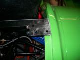
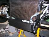
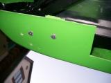
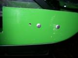
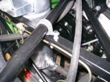
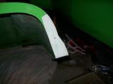
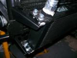
The radiator doesn't fit well to the brackets because there is either a gap at the top, or a gap at the bottom. I spoke to Mark at the factory about this, and he told me that they just put a spacer at the top. You can see this in the pictures, and where I had tightened the bolts it had bent the brackets out of shape.
I cut some 6mm tubing for the bolts to pass through at the top and then tightened it all up. The radiator seems much more secure, and also it has straightened out the brackets nicely now that all the surfaces sit flat (forgot to take a picture of the final result though).
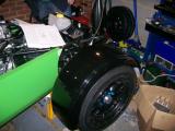
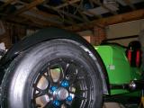
Fitting the cycle wings is a job that could wait, but since we've got a spare hour until we need to go out we decide to get it started.
They bolt to the front upright using 3 bolts, and then it's our job to fit the arches to the brackets. We decided it would be easiest to drill 4 holes in measured positions on each bracket, then move the wings into position, mark them from underneath, drill, and then hope they line up.
The metal is very tough and it takes a while to drill through all 8 holes (4 on each bracket). We put the wings into place and they immediately transform the look of the car, but we leave the fixing to another time since we need to get out for a friend's birthday.
Laurence
 |
 |
 |
 |
 |
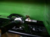
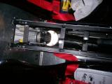
I tried the handbrake the other day and it wasn't working. It would bite, but not nearly enough to stop the car from rolling down a hill for example. I had a look to see what was wrong, and the springs on the handbrake were not being moved hardly at all when the handbrake was applied.
I went back to check the manual, and I quickly spied a problem. The ends of the handbrake cable go over the hook on each calliper as already fitted, but then the cable must travel down through the round bracket beneath the lever, so that when the cable is pulled, the force has a completely vertical motion which will be translated into pulling the hook down and compressing the spring.
Easier said than done though as the cable is very tight. I slackened it right off at the top, which then made the job much easier. I removed each cable from the hook, poked it up through the bracket, and then put it back over the hook again.
Immediately I can see how much better it will work, and when I try the handbrake you can see the springs being compressed which didn't happen before. So I adjust the slack out of the cable and call it a night there. I don't want to start anything new tonight.
Laurence
 |
 |
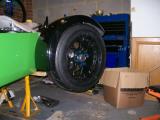
We have already drilled the holes into the cycle wing brackets, so now all we need to do is position the arches into place, mark them, and then drill through, leaving a hole that we can bolt through.
We followed the manual's guidelines for positioning and then marked onto the arch from the underside using the holes we had drilled in the bracket as a template.
Now we just drilled through and then bolted the M5 screws down. The only problem is that we are out of foam tape which should be fitted between the bracket and the arch, so we fit them loosely until we can get some more.
Laurence
 |
 |
 |
We put the manifold back on the engine tonight ready for exhaust mounting. There are some studs provided with the kit, but the bike breaker kindly sent me the manifold bolts with my engine, so I thought I may as well use them instead as they are 800 miles old (like the rest of the engine). A couple were very tight and I had to cut down an Allen key to gain access, but it went in ok.
The exhaust is supposed to fit over the manifold with a sliding joint, but it will go no further than 35mm down the shaft. Even with loads of WD40, it still refuses to move any further down, and the tail pipe is hitting the rear arch so it MUST go on further. We take it off to examine...
There is an inner heat weld inside the silencer exactly 35mm down the shaft, so we take a Dremel to it and try to smooth it out. It makes a bit of a difference, but in the end brute force wins and the exhaust mounts up nicely.
It's about 1cm away from the body, so under a small amount of tension when pushed tight to the mounting point. This is probably a good thing though as it will prevent vibration.
The exhaust mounting is not documented, so I checked with Westfield first, and the steps are here.
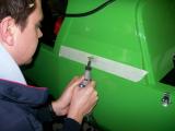
You need to use a bracket very similar to what the reverse box lever fixes to. Mark and drill this in the correct location for the exhaust, but make sure you only drill through the body and not the aluminium panel. Now you need 2 M6 bolts about 25mm in length to secure the bracket to the body. If you remove the rear wheel you can actually fit your hand between the bodywork and the alluminium panel, where you can place a washer and a nut on each bolt to secure the bracket.
Now you mount the exhaust bobbin. I had been wondering what this thing was used for since day 1, and now I know! Secure this to the bracket from underneath. You can now re-fit the exhaust and the other end of the bobbin will poke through the exhaust bracket, so just bolt it down using a washer and a nut. It looks very nice indeed.
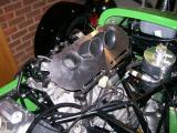
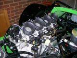
Before I went to bed I fitted the throttle bodies to the engine. They had been in a bag since I sent the fuel rail off to Westfield with the ECU loom (some 2 months ago) and I'm bored of waiting for it, so I fitted the throttle bodies without the complete rail.
Laurence
 |
 |
 |
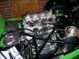 |
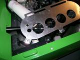
We're STILL waiting for our fuel rail and ECU loom from Westfield, so I decided that I'd get everything assembled anyway, then it would just be a case of removing the air filter plate to fit the fuel rail, and then put it back on again.
I looked at the plate and couldn't work it out, so I checked another build diary and it seems that there are rubber trumpets. I looked at the standard Hayabusa airbox and I could see the trumpets in there, so is took it apart and found a sensor too. This is obviously the inlet air temperature sensor and it will be needed to satisfy the ECU, so I remove that too.
I am left with 4 trumpets, the clamps, and the sensor. The trumpets fit over the throttle bodies and clamp into place, but the middle trumpets are twice the size and do not fit under the Westfield foam filter.
I can't think that you just cut them down as NA engines are very fussy about equal flow, so I decided to leave it and see if Westfield can supply some short trumpets.
Laurence
 |
 |
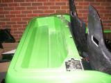
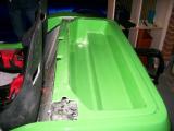
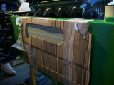
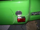
This job was probably as scary as the exhaust manifold cutting, and a job that would ruin the same large section of bodywork if I got it wrong.
I started by taping up the fuel filler neck on the tank, as the last thing you want is a load of body dust clogging up your fuel filter and injectors.
I then covered the entire area that the hole would be cut in with masking tape, and then started marking. The way I decided to do it was to mark a cross INSIDE the bodywork which was the exact centre of the tank's filler neck. I then drilled a small hole through the centre from the inside. Now, when looking from outside you have a centre mark, so I set up my hole saw, drilled through with the drill bit, checked it was central on the inside, and then made contact with the hole cutter.
The hole is absolutely spot on and I'm absolutely delighted. That is until a few minutes later when I realise that the tank wasn't central when I drilled the hole! I break into panic thinking I've wrecked the hole thing, because there is no way the lower roll bar bolt will go in on the right hand side as the tank is too close.
There is actually a lot of room for maneuver with the hole though, so I made it larger on the left hand side, which allows the whole tank to shift over too, and the roll bar bolt fits as it should.
I was very lucky and really should have checked that the tank was central again before cutting, but it's just one of those things! Still, I got away with it...just!
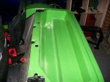
All that's left is to connect the rubber hose to the tank, and then connect it to the fuel cap, but it's impossible to get the rubber hose over the tank filler neck without removing the tank, so I would advise you fit the rubber hose when you fit the tank. I had to remove the entire thing including all fuel lines to get mine on!
Once this is done it's all very simple - the hose needs clamping onto the tank and onto the fuel cap, and then the cap can be bolted down using the supplied fixings.
Laurence
 |
 |
 |
 |
I decided to have another look at the loom. Using the loom identification tables in the big manual, I was able to work out what most of the wires were, and how they plugged into the digital dash loom. Everything is fine except I can't work out how to fit the indicator switch, nor the headlight switch, fog light switch, and the other bits that a standard dash would use. I'll ring Westfield about it as I can't see how it will work.
Laurence
I called Mark Walker at Westfield today about the throttle body trumpet problem and he confirmed that we need to pick 2 short ones up. Searching a few forums, it seems that are rare as rocking horse poo, and Suzuki charge an absolute fortune for them, so a gave Malc at Yorkshire Engines a call.
Before I had even explained the problem in full, Malc had already started with, "That's right you've got 2 long and 2 short, and you're probably after another 2 short aren't you?"
He didn't have any laying around, but he said he was almost certain he could find me one the next day. Fingers crossed...
Laurence
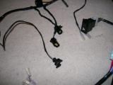
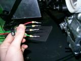
The front and rear lights all need wiring into block terminals so that they are compatible with the Westfield loom. I have bought a tool suitable for crimping the tiny uninsulated needle terminals from Vehicle Wiring Products.
http://www.vehicle-wiring-products.eu/VWP-onlinestore/terminalsnonins/noninscrimps.php
I just snipped the original terminals from the lights and followed the Westfield manual instructions. It's actually really neat how the block terminals are made up.
I started on the rear lights and repeated the process for the fog light and the front lights too. Once I'm happy they all work I'll cable tie everything out of the way.
Laurence
 |
 |
Malc delivered as I knew he would. He found me a complete 2006 Hayabusa airbox for £40 and has sent it down so it should be here tomorrow.
Great work Malc, and in double-quick time too. Thanks mate :)
Laurence
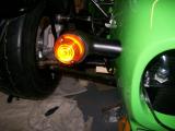
Whilst we are STILL waiting for a fuel rail and a few other assorted parts which prevent us from starting the engine, we decided to fit the indicators into place. This is another job that will build up and cost time at the end of the project, so it's good to tick these off the list now.
Kriss and I marked up the nose cone using the exact measurements as documented in the manual. We used a spirit level to make sure they were straight though, and then measured the holes both sides to ensure they were symmetrical.
Once happy we drilled through the marked holes.
Kriss left me to bolt the indicator pods into place and wire them whilst he and Matt carried out some major work on the aeroscreen (more on that later).
I fed the indicator wires through the holes and bolted the indicator pods into place. Now the lights just had to be fitted into the pods. It was quite tricky though as the holes in the pods don't quite line up with the holes in the lights.
The trick was to fit rivets into 2 of the holes, then force the whole unit over with about a 1cm gap between the light and the pod. Once all 3 rivets were aligned then they just needed fastening with the riveter, and then I made up block terminals for each side.
Our aeroscreen was very wrong, so Matt and Kriss made some adjustments. There really is nothing I can say about fitting the screen - it's purely trial and error. Don't worry about slotting the holes because the washers you fit are large enough to compensate.
We eventually reached a position which we liked, so we bolted it down, and then riveted the central bracket into place. We had to shorten the bracket slightly, but it fits really nicely now. Matt and Kriss finished it off with some black edge trim, and I'm so impressed with how it looks.
A sterling job by both Kriss and Matt.
Now the side repeaters. The Westfield manual says to fit them on the body, but every car I have seen has them on the scuttle. I believe the measurements were 50mm from the bottom and 150mm from the front.
Kriss drew out the shape in the manual onto the scuttle using masking tape, and then out came the Dremmel. We broke a few blades, but a really neat hole was cut and the side repeater fits very tightly, so we did the same for the other side and called it a night there.
We forgot to take a final picture with the repeaters fitted, but believe me they look great.
Laurence
 |
 |
 |
 |
 |
 |
 |
 |
 |
 |
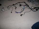
I spoke to Mark Walker at the factory today and told him about the loom. He asked me to send him a picture which I did, and he quickly confirmed that I had been sent a racing loom, which has no facilities for windscreen wipers, heater controls, indicators, the list goes on...
It's near impossible to make this fit a road car and they can't understand why it has been sent to me. The problem is I have taken quite a bit of time labeling it up and now it has to go back :(
I have asked them to get the standard loom and more of our outstanding parts out to us next day.
Laurence
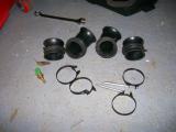
The new trumpets from Malc @ Yorkshire are here to replace the larger inner trumpets. I removed the old ones and dropped the new ones into place. They are perfect.
The filter plate is designed to fit over them exactly how the standard airbox does, but first a couple of holes must be made in the plate. One is for the air temperature sensor, and the other is an air feed to the PAIR valve (under the exhaust manifold).
The holes are very easy to cut and are finished in no time. I put the 3 securing clips onto the edges, but there is no point fitting the plate yet as it blocks the fuel rail which we are STILL waiting on from Westfield.
Off to the gym now...
Laurence
|
 |
 |
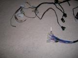
The correct wiring loom arrived today along with a couple of other outstanding parts. Immediately I can see the difference in the looms, and how the rocker switches connect. I started to label up the new loom but didn't do too much else on it this evening.
Laurence
 |