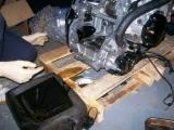
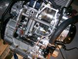
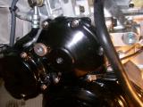
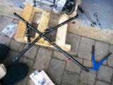
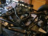
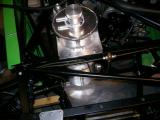
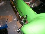
It's New Year's day, most of the alcohol has gone (along with the headache), it's the evening time, Westfield are still shut for the Christmas period, and we're running out of things to do with the lack of driveshaft on one side, so we decide that now would be a good time to tackle the dry sump system. Up until now, then engine has lived in a plastic crate on a pallet straight from Yorkshire Engines, so we lift it out. The box weighs a tonne so I was really not looking forward to this, but once we took the exhaust manifold, ECU, wiring loom, fuel pump, and all of the other odds and ends out of the box, it felt a lot lighter.
In fact, once we had a decent grip on it, Matt and I could comfortably lift it out of the box and on to the pallet. No engine hoist needed here! We had a box full of the dry sump kit, and a set of instructions that were faxed to Matt and really weren't that clear at all as a result - this could be interesting!
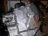
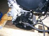
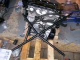
We tilted the engine over being careful not to crush anything, and then took the sump off. The engine is virtually new at 800 miles old (we opted for one that was literally run in instead of brand new so we wouldn't have to run it in ourselves). Due to the young age of the engine, the bolts came off like they were brand new.
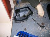
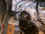
After 14 or so bolts were removed the sump literally fell off exposing a very healthy looking inside. The dry sump is much more shallow that the original, so you need to remove the original oil pickup and discard it, and then you need to remove the oil return feed and shorten it so the new sump can be fitted. Stupidly as I was refitting the pipe I dropped the bolt into the gearbox and sent myself into a state of panic thinking I'd never find it. I got my magnetic retrieval tool and found it almost immediately though - phew!
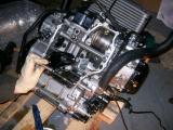
The new sump could now be fitted to the engine. Westfield supply 2 new sump gaskets and a baffle within the kit, as well as new sump bolts to replace the original bolts. The order is gasket on to bottom of engine, then baffle, then another gasket, and then the sump itself. This seals the baffle and the sump itself. You then just fix it back into place using the new bolts and spring washers. The next job is to fit the oil pump, but that's probably a job for another evening as it's cold and I'm hungry.
Laurence
 |
 |
 |
 |
 |
 |
 |
 |
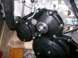
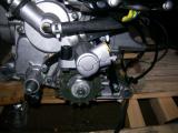
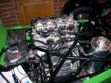
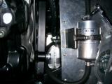
Now the dry sump is fitted the scavenge pumps can be fitted which pull oil out of the sump and into the remote oil reservoir. This is a lot more complicated than it sounds though - it runs off the engine like an alternator does, but you have to extend the rotation of the crackshaft out so that the pump can make use of it. Luckily Westfield's dry sump kit has an excellent solution to this.
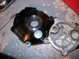
You start by removing the starter motor drive cover and are immediately faced with gears and other stuff that you would be a bit reluctant to disassemble, but then immediately you learn you have to remove them. Luckily I have the workshop manual for the engine if I get stuck.
You then take off the starter motor clutch cover next to it, allowing the whole unit to be removed which roughly resembles a figure of 8 shape. On the larger of the two covers, you need to remove the centre cover which covers a bolt, and you replace it with the Westfield supplied insert which has a hole in the centre for a shaft to run through it.
Now the bolt needs to come off the starter clutch, but you will find that turning it with a ratchet will turn the engine instead of loosening the bolt, so you need to shock the bolt off. Strike the ratchet with a hammer a few times instead of pushing with your hand and the bolt will free itself.
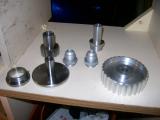
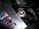
The pulley drive flange has 3 drive pins which fit into the starter clutch now that the bolt is removed, and you quickly start to see exactly how the whole set-up works. You need to insert the 2 roll pins into the drive flange before fitting into place. I found the best way to do this was with 2 people, a pair of fine nosed pliars, and a small hammer.
Once the pins are in place, the pulley drive flange can be offered up to the starter clutch, and secured into place with a few taps of the hammer. once this is in place, the starter clutch cover can be put back into place with a new gasket, and you quickly see why you had to put the Westfield part had to be fitted to the cover - the pulley flange pokes right though it. With the pulley fitted to the shaft, you can tighten everything back up again.
A new bolt needs to be fitted to secure the pulley assembly into place - you can get this tight, but it will spin the engine before you hit the specified torque (like when you took it off), so don't use threadlock yet. You can tighten it when the drive flange is fitted to the engine - read on to the later section for details...
Laurence
 |
 |
 |
 |
 |
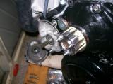 |
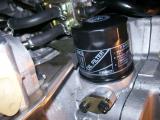
Continuing on with the dry sump fitting, now that the pulley to power the scavenge pump was installed, it was time to fit the scavenge pump itself. The pump fixes into the bracket just fine, and then the bracket uses a few existing bolts to fit onto the engine, but the oil filter needs to come off to remove one of the bolts that the bracket uses, and it's stuck fast. No amount of twisting with my hands will get the filter off, so I'll need a tool, and everything I have tried won't work. Not a huge amount of work done on the engine tonight then!
Laurence
 |
Carrying on from the other night, to remove the oil filter I tried using an oil filter wrench which is basically a strap which wraps around the filter, and then a ratchet is used to tighten the strap on to the filter and the twisting motion breaks it free. It doesn't work though because the filter is done up 2 whole turns after the seals touch - it's normally half a turn on a car, so it's very, very tight!
Eventually, a huge plumber wrench does the job by crushing the filter to get a grip on it, and then it just twists off. Now with the filter removed I can remove the bolt that was being blocked by the filter, and fit the oil pump bracket to the engine, but the bracket doesn't fit that well when you try and secure it to the engine, and I had to open up a couple of the holes a little. Even with this, it's still not a great fit. The trick eventually was to get all of the bolts in place very loosely, and then tighten each one a bit at a time which shapes the bracket to fit.
Everything looks fine until I try to fit the new oil filter, but it fouls the oil pump bracket. The only choice is to shave the edge off the bracket, but directly beneath is the open oil filter thread. I don't want swarf getting in, nor do I want to remove the bracket again due to its poor fit, so I cover the entire area over and begin filing. After a short while, enough of the bracket has been taken off and the filter fits just fine.
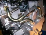
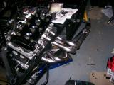
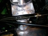
Now with the scavenge pump fitted, the oil pipes that come from the sump must be connected to the scavenge pump. This is quite fiddly because You can't get a ratchet to the Allen head bolts in some cases, so you have to use an Allen key a quarter-turn at a time, but you get there eventually. It was a process of elimination working out which pipe went where, but I got there in the end.
I then fitted the two metal pipes to the scavenge pump itself, again, using a process of elimination. This is even more fiddly though, and I had to file down the weld on one of the pipes as the small nut kept hitting the weld and wouldn't thread.
Now all that remains is to connect up the pipes using the flexible hose. The easiest way to do this is to slacken off the bolts on the metal pipes so you can move them around. This helps loads when trying to slip the flexible hose onto both ends of the metal pipes.
It wasn't long before I ran into a problem though - with the right-most pipes connected, the left pipe touches it. This is with all pipes not tightened - it will be impossible to tighten them further too. Something is wrong, so I'll have to speak to Westfield and find out if I have got the pipes fitted in the wrong places, or if the pipe(s) themselves are wrong!
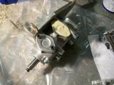
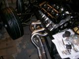
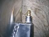
Just before I finished for the night, I remembered that Westfield need the Hayabusa wiring loom so that they can modify it, so I packed it up ready. In addition to this they need a section of the Hayabusa fuel rail. I understand that a bike runs lower fuel pressure, so they only feed fuel into the fuel rail. However a car runs higher fuel pressure, so the fuel rail must have a send AND a return, so they need the last section of fuel rail and they modify it into a T piece to form a return.
You need to unscrew the injectors and pull them out, then the fuel rail sections just pop out when you pull them. You need to send Westfield the left-most section in the picture below, which is the opposite side to the brass feed on the right.
Laurence
 |
 |
 |
 |
 |
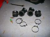
In today's delivery from Westfield was a new scavenge pipe. Earlier in the diary I posted a picture where the two scavenge pipes were touching. I sent this same picture to Westfield and they agreed that it was not right, so they sent me a new one to try.
Immediately the new pipe looks better, but the entire right-hand pipe has to come off to gain access to fit the new one, so lots of fiddling and it looks a lot better. The flexible pipes are very solid and are a bit of a challenge to get into place, but eventually they went on and the new pipe did the job perfectly.
With these fitted, the only thing left to do is connect the pump pulley to the engine using the supplied belt. It's very tight, and the engine needs to be gently turned which eases the belt into place. It looks very near the front of the scavenge pump pulley, but it's very tight and it won't go on any further. Hopefully it will be ok.
I used the allen head bolt that was fitted onto the starter clutch earlier in the dry sump fitting process to turn the engine which in turn spun the pulley. This bolt will need to be torqued and threadlocked which I'll do once I have changed the output sprocket for a driveshaft flange to give me something to lever off, otherwise the engine will just spin like it's doing now to fit the belt.
Laurence
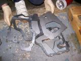
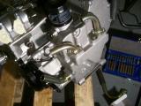
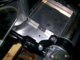
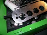
Before the engine can be fitted into place, there is quite a bit of preparation work required. Luckily, this section of the build is well documented in the Megabusa manual. You start by fitting the brackets to the clutch slave cylinder, but the image in the manual had them on the wrong way. The 2nd picture shows it fitted, so I used this one to work it out.
In order to bolt this to the engine, you first need to remove the cover that's in the way (pictured below). This covers the chain sprocket, and the original clutch mechanism. A few bolts and the whole thing lifts off, allowing you to fit the new clutch slave cylinder in place and tighten.
Now you fit the engine brackets at either end of the engine. The threads on the engine are extremely soft and I cross-threaded one without any effort at all, but I managed to sort it out by removing the bolt, and threading it straight with some force. I was worried I would have to use a tap, because the bolts have a peculiar pitch to them. Whilst I was having fun with this, Matt finished fitting the removable reverse box panels.
Matt and I are were both heading out for the evening, so we leave it there.
Laurence
 |
 |
 |
 |
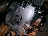
Carrying on from yesterday, the engine frame fits to the brackets we fitted previously, but we had forgotten to fit wiring loom saddles to the frame, so we skipped back to the wiring loom section and Matt quickly drilled and riveted them into place.
The frame fixes to the engine using the stud, washers, and bolts. With this in place the frame can then be attached to the brackets. Matt and I found this an extremely tight fit and had to use a lot of force and gradual tightening to make it work. With everything tightened, the engine was now fully ready for dropping into the chassis.
UPDATE:
We later found out this tight fit was due to the cross-frame needing to sit the other side of the brackets. The sequence is bolt, washer, engine bracket, engine frame, washer, nut. We had the bracket and frame the wrong way round. Shame we didn't realise this until we had already lifted the engine in (see later post).
Laurence
 |
 |
We plan to install the engine this coming Saturday, but there are a couple of things that need doing before this can be done.
The drive pulley for the scavenge pump must be threadlocked and torque tightened, and the chain sprocket must be removed and replaced with a propshaft flange since the car does not use a chain.
The problem is, the chain sprocket just spins freely, so how can you take it off? You need to find the gear shift leaver and place it on the gearbox selector. It attaches on the splined shaft which is virtually next to the chain sprocket. Now get the car into gear, and it will couple the gearbox to the engine giving some resistance to push against. You have to remove a securing bolt with an Allen head socket. Now you need an impact wrench to shock the chain sprocket bolt off. With the bolt removed, the sprocket just pulls off.
Now you can put the output flange in its place and refit the securing bolt You need to threadlock it and torque tighten it, but you will find that the flange will begin to turn before you can get enough torque to the bolt (as it exceeds the engine resistance). You need to fit an M8 bolt through one of the holes in the flange and lever off it with a pry bar against the rotation of the flange and then you can tighten the bolt. Now refit the securing Allen head bolt.
You also need to threadlock the drive pulley bolt that you installed for the oil pump. This is done in an almost identical way, except for one small problem, I had the engine in 1st gear, so 10Nm of torque on the bolt gave about 30Nm on the output flange, so 50Nm was giving about 150Nm on the pry bar my Dad was holding. The solution is to put the engine in 6th gear where the gearbox gives hardly any torque multiplication. The bolt could be torqued easily now.
Engine preparation done - bring on Saturday!
(Didn't take any pictures - sorry!)
Laurence
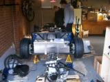
This is the milestone that any car builder looks forward to. The day the engine goes in is the day that the rolling chassis becomes a car, and the light at the end of the tunnel becomes visible.
It's around noon, Kriss and Jonny have just arrived, and the engine is fully prepared ready for fitting. We walk around for a bit weighing up the best way to go about it, and decide to move the engine and pallet over to the offside next to the engine bay. Kriss then suggested that we cover the top chassis rail so it didn't get scratched by the engine, so some packing card was taped over it.
The engine can be lifted quite comfortably by two people, but due to the chassis still being quite high on axle stands, there were 4 of us. Kriss and Jonny and I lifted the engine up to about chest height, but we couldn't get it into the engine bay as we were all in each others way.
Jonny was already looking at numbers for engine crane hire, but I knew it would go in manually. The problem was getting the engine into the engine bay, so I suggested that Matt should stand inside the engine bay so Kriss and Jonny could pass it to him to support, then he could pass it to me to support and duck out, leaving the 3 of us to lower it down.
In the end Matt just put one leg into the engine bay and one outside. Jonny and Kriss lifted the engine to around chest height, passed it towards Matt so the 3 of them supported it, then he slipped his leg out whilst I supported part of the engine frame. Now we just lowered it down into position.
Problem! It won't sit on its mounts. If it sits correctly on one side, the other side was about an inch too low. We tried a few things, but nothing would line up. Jonny took a look at the manual and quickly worked out that the engine frame was fixed on the wrong side of the engine brackets at either end (see previous post here for more details).
So back out the engine came, and we quickly swapped the frame to sit the other side of the brackets. We had to remove the whole thing, but it didn't take long. We lifted the engine back in using the exact same technique as before, but this time it sat on its mounting locations perfectly.
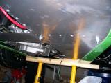
The engine was finally in - well nearly. It's not bolted down, but you can't bolt it down until you have the bodywork in place. The trick is to fit the bodywork, and then the exhaust. When the exhaust lines up with the bodywork for mounting, you can drill your holes in the engine mounting brackets and then bolt it down.
I think that this went fairly well, except the pictures. I let Matt take them and they are all blurry (again). Sorry!
Laurence
 |
 |
 |
 |
 |
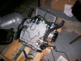
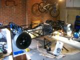
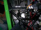
Tonight Matt and I had a few loose ends to tackle. Connecting the engine output flange to the prop shaft, fitting the radiator expansion tank (header tank), fitting the dry sump oil tank, and fitting the fuel pressure regulator.
The first task is definitely a 2 person job. I laid on the floor with the torque wrench whilst Matt held a spanner on the other end of the bolts. We tightened them all, and then one by one we loosened a nut and bolt, applied thread lock, then re-tightened and torqued them. To stop the prop spinning we put the engine in gear each time to lock it. Once all 4 were tightened we marked each one so we could check for movement over time.
Whilst we were there we fixed the clutch line onto the slave cylinder.
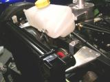
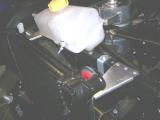
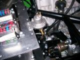
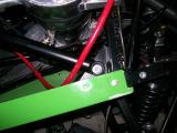
The oil tank fits really nicely. It has a right angle bracket at the bottom which fits perfectly over the frame rail at the bottom and it holds really well. Now you just hold it straight and drill through the top bracket and then all the way through the chassis rail. With this done you can just bolt it down with some M6 bolts and washers. We moved it as far over to the offside wheel as we could to allow room for the battery tray. The tank bracket covers the last letter of the chassis number etched into the frame rail. Hopefully this is not an issue though as the number is duplicated on the identification plaque.
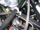
Now for a job I had looked at several times and just given up on - the expansion tank. Simon from the factory had send me some pictures to help me out. The fat tube points to the rear of the car, and the header tank fits on using the two plastic mounting brackets on the tank itself. It bolts to the same chassis rail that the horn is fitted to.
The flat bracket bolts to the rail so you just drill straight through both sides and fix into place. The second bracket comes off at a 45 degree angle to the car, so you have to mount it to the chassis using the supplied black bracket. It fixes underneath the chassis rail, and then you bolt it to the 45 degree bracket coming off the tank. This now feels nice and secure.
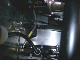
The fuel pressure regulator is another item which is left completely out of the manual, but it fixes to the chassis bulkhead rail. There were a few options for fitting, but I chose to use self tapping screws and locking washers as they were supplied with the kit.
The inlet sat very close to the gear change quadrant, but by the look of the unit, the inlet can be on either side, so I removed it and fitted it to the other side and swapped the blanking plug over too. These were on very tight and there was evidence of some thread seal, so I used thread seal when re-fitting both the nipple and the blanking plug.
I looked at the battery tray, drilled a couple of holes, and then realised that the tray's securing strap was missing, so I called it a night there.
Laurence
 |
 |
 |
 |
 |
 |
 |
 |
 |
 |
 |
Just a small update on the engine side of things as we've had a busy day on the bodywork. The metal radiator pipes need securing using P-clips, but they sit too low if you fix them to the body, so you need to make up some spacers.
B&Q sell 6mm (M6) aluminium tubing for next to nothing, so I just cut some of this to length, drilled through the chassis rail, and bolted it down. It makes the pipe sit perfectly, and this is what the factory tend to do with their cars too.
I need to make an even longer spacer for the lower pipe, but I don't have a bolt long enough so I'll leave that for another day.
Laurence
 |
We put the manifold back on the engine tonight ready for exhaust mounting. There are some studs provided with the kit, but the bike breaker kindly sent me the manifold bolts with my engine, so I thought I may as well use them instead as they are 800 miles old (like the rest of the engine). A couple were very tight and I had to cut down an Allen key to gain access, but it went in ok.
The exhaust is supposed to fit over the manifold with a sliding joint, but it will go no further than 35mm down the shaft. Even with loads of WD40, it still refuses to move any further down, and the tail pipe is hitting the rear arch so it MUST go on further. We take it off to examine...
There is an inner heat weld inside the silencer exactly 35mm down the shaft, so we take a Dremel to it and try to smooth it out. It makes a bit of a difference, but in the end brute force wins and the exhaust mounts up nicely.
It's about 1cm away from the body, so under a small amount of tension when pushed tight to the mounting point. This is probably a good thing though as it will prevent vibration.
The exhaust mounting is not documented, so I checked with Westfield first, and the steps are here.
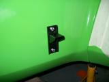
You need to use a bracket very similar to what the reverse box lever fixes to. Mark and drill this in the correct location for the exhaust, but make sure you only drill through the body and not the aluminium panel. Now you need 2 M6 bolts about 25mm in length to secure the bracket to the body. If you remove the rear wheel you can actually fit your hand between the bodywork and the alluminium panel, where you can place a washer and a nut on each bolt to secure the bracket.
Now you mount the exhaust bobbin. I had been wondering what this thing was used for since day 1, and now I know! Secure this to the bracket from underneath. You can now re-fit the exhaust and the other end of the bobbin will poke through the exhaust bracket, so just bolt it down using a washer and a nut. It looks very nice indeed.
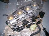
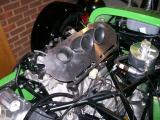
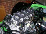
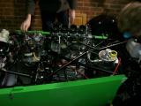
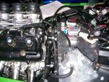
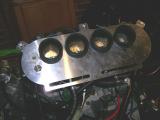
Before I went to bed I fitted the throttle bodies to the engine. They had been in a bag since I sent the fuel rail off to Westfield with the ECU loom (some 2 months ago) and I'm bored of waiting for it, so I fitted the throttle bodies without the complete rail.
Laurence
 |
 |
 |
 |
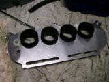
We're STILL waiting for our fuel rail and ECU loom from Westfield, so I decided that I'd get everything assembled anyway, then it would just be a case of removing the air filter plate to fit the fuel rail, and then put it back on again.
I looked at the plate and couldn't work it out, so I checked another build diary and it seems that there are rubber trumpets. I looked at the standard Hayabusa airbox and I could see the trumpets in there, so is took it apart and found a sensor too. This is obviously the inlet air temperature sensor and it will be needed to satisfy the ECU, so I remove that too.
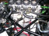
I am left with 4 trumpets, the clamps, and the sensor. The trumpets fit over the throttle bodies and clamp into place, but the middle trumpets are twice the size and do not fit under the Westfield foam filter.
I can't think that you just cut them down as NA engines are very fussy about equal flow, so I decided to leave it and see if Westfield can supply some short trumpets.
Laurence
 |
 |
I called Mark Walker at Westfield today about the throttle body trumpet problem and he confirmed that we need to pick 2 short ones up. Searching a few forums, it seems that are rare as rocking horse poo, and Suzuki charge an absolute fortune for them, so a gave Malc at Yorkshire Engines a call.
Before I had even explained the problem in full, Malc had already started with, "That's right you've got 2 long and 2 short, and you're probably after another 2 short aren't you?"
He didn't have any laying around, but he said he was almost certain he could find me one the next day. Fingers crossed...
Laurence
Malc delivered as I knew he would. He found me a complete 2006 Hayabusa airbox for £40 and has sent it down so it should be here tomorrow.
Great work Malc, and in double-quick time too. Thanks mate :)
Laurence
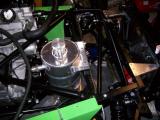
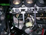
The new trumpets from Malc @ Yorkshire are here to replace the larger inner trumpets. I removed the old ones and dropped the new ones into place. They are perfect.
The filter plate is designed to fit over them exactly how the standard airbox does, but first a couple of holes must be made in the plate. One is for the air temperature sensor, and the other is an air feed to the PAIR valve (under the exhaust manifold).
The holes are very easy to cut and are finished in no time. I put the 3 securing clips onto the edges, but there is no point fitting the plate yet as it blocks the fuel rail which we are STILL waiting on from Westfield.
Off to the gym now...
Laurence
|
 |
 |
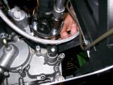
Although not really required, it's very sensible to fit an oil pressure sender to the engine so we can keep an eye on things. It makes even more sense since all of the wiring is already in place on the loom, and the DASH2 can have 4 inputs, so we might as well make use of them.
The idea is that we'll set an alarm if the pressure drops too low, and the DASH2 unit will tell us about it, so we won't even have to monitor it constantly ourselves.
I have heard that when warm, oil pressure drops as low as 1.0bar on the Hayabusa engine, so the alarm will have to be set pretty low to avoid it becoming a nuisance. Thinking about it, with 9,000rpm and a warning as low as 0.8bar, by the time we've responded to the warning it will probably be too late. Even so, might as well fit it.
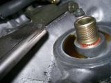
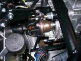
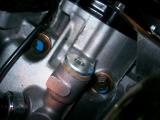
The oil pressure sender that we purchased from Westfield fits in the same location that you connect an oil pressure gauge to when testing pressure during service. It's just in front of the oil pressure switch.
I removed the blanking plug, and then realised that the sensor thread was miles too small. Some kind of adaption is needed - it looks like an M16 thread. I'll call Westfield.
Laurence
 |
Tonight is a big night - we're going to try desperately to fire up the engine. I spoke to Dave @ Westfield today, and he confirmed that an adapter is needed to make the oil pressure sender fit, but they had forgotten to send it to us.
Mark said that it was not a good idea to start the engine without it which I was gutted about, but I had a plan. I looked at the wiring diagram for the Hayabusa engine and I could see that the oil pressure warning was very simple - the dash warning light is given a 12v feed, which then connects to the oil pressure switch, which then connects to earth, so when there is enough oil pressure the pressure switch breaks the path to earth, and therefore the circuit, which prevents the light coming on.
We decided we could use the oil pressure switch by giving it a 12v feed and placing a multimeter inline. With the engine off it reads 12v, so our theory is correct. We can happily use this as an indication of oil pressure. If it shows 0v then oil pressure is fine.
We had a lot of work to do though. We had our fuel rail at long last (3 months I think it took!!!) I connected the fuel rail segment to the throttle bodies. Also in the delivery was the M8 bolts and washers needed to bolt the engine down to the chassis. The holes were already drilled by me previously, but needed opening and adjusting slightly as they weren't quite perfect. Some of the bolts had to be fitted upside down as access was very tight, but we got around and tightened them all up.
Jonny was round to help us for the evening, so he and Matt finished the bolting down whilst I started connecting up the throttle bodies and the fuel pressure regulator to the fuel lines. I had trouble fitting the rubber lines to the solid lines that terminate by the passenger bulkhead as access was very tight, but Jonny was able to do it.
We fitted the water temperature sender and oil temp senders in their relevant locations, and then began to fill up the coolant. Matt put a cup of coolant in followed by a cup of water to get the mixture 50%. We were surprised at how quickly the expansion tank filled up. It seemed to fill up the expansion tank and then just stop without draining down into the pipes or the engine. You got the odd bubble now and then though, so we just squeezed all of the pipes. This moved a lot of air and the engine started to take the water from the tank. I was surprised at how little water the car took though.
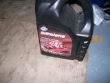
Whilst Matt was finishing the coolant, I filled up the oil tank with Silkolene Pro 4 10W40 which is a fully synthetic motorcycle engine oil. It's blood red in colour which looks awesome! The engine with dry sump takes around 6 litres.
Kriss and Dan popped over, then got bored so they went to the pub, so it's just Matt, Jonny and I. Kriss and Dan came back later on, saw no action, poked some fun at us, and then left again.
We had just a few things to do, but it was getting late. We double-checked that all of the sensors were connected, and that everything was clear of the prop shaft. We had some wiring to do with the connecting of the ECU loom to the main loom. Things like the gear position sensor and the rev counter had to be connected into the main loom, so I made up a block connector for this. It took a little while as it was in quite a fiddly location. We also had to run the power cables through a grommet along with the ECU loom. The last thing we needed to do was connect the ECU loom into the fuel pump fuse.
We went over everything one last time and then turned the ignition on - we heard the fuel force its way into the fuel rail and then back. We left it for 15 minutes as the manual says and inspected for leaks - there didn't seem to be any leaks at all. Result.
So here we go, the car is in neutral, the fuel system seems to work just fine, oil is in the engine, so lets give it a go...
I turn the key and it cranks for a few seconds, then fires into life. Wow it seems really loud. I let it run for a few seconds and then cut the engine.
"Did it start?" Matt asked. He thought I was cranking the whole time, but it was the engine running on its own steam, but obviously very rough. I got scared though which is why I turned it off so fast. I don't know why - I guess it's just such an expensive thing to have malfunction.
We are all very proud of ourselves, so we started it again, but for longer this time. The car settled down to a steady idle very quickly, and the oil pressure light is off, so that's good. We gave the throttle a couple of blips and were amazed by the throttle response.
We cut the engine, talked for a bit, and then notice an oil leak. It was coming from the oil tank bottom outlet that feeds the sump. Tightening it is very difficult because there is a chassis rail in the way, but we manage it, or so we thought.
The leak is still there and we can't turn the boss any more because the chassis rail is obstructing it. It's getting late too. The only way we can do it is to remove the tank. I cleaned a bowl for the oil and we removed the hose that connects the tank to the sump and the oil slowly drained into it. Once empty, we removed the tank and tightened the boss as much as we could and clean up the oil on the chassis. We then refitted the tank, refilled it with oil, and then crossed our fingers that the leak had stopped.
We gave it another go, and left the engine running for a minute or two then stopped it. Wwwwooooooo! Lucky we did - massive oil leak! Worse still, the scavenge pump belt is on the floor. How the hell has that come off?
The oil leak was coming from the top of the scavenge pump that goes to the oil cooler. Jonny gets a spanner onto it and it turns out I've only tightened it finger tight. It takes ages to tighten due to such limited access, but Jonny did it eventually. Silly mistake, but this is why you start the engine and monitor it so closely before even thinking about hitting the road.
Looking at the dry sump instructions, I had forgotten to fit the front plate to the drive pulley, which is what retains the belt. The rear one was on, but the front one was missing. Sure enough, it was in the dry sump box along with the retaining bolts.
It's was way past our bed-time, and Matt had already had enough but Jonny and I just couldn't leave the car alone. I was hoping the engine didn't have to come out again to gain access to the pulley, but it was just a case of putting the engine into gear and then un-torquing the bolt that secures the drive pulley into place. Upon doing this, the pulley just pops out allowing us to fit the front plate to it, then we just popped it back into place.
We put the belt back on and then finished for the night. Jonny was a real asset tonight, and I doubt I would have got the engine started without his help. More importantly though, I went to bed on a high that the belt and pulley was sorted, instead of worrying that the engine might have to come out to gain access.
Laurence
 |
 |
 |
 |
 |
 |
 |
 |
 |
 |
 |
 |
I'm still really happy about the engine being run yesterday - it felt like such an achievement, and in the back of my mind I was prepared for a total failure due to something not being connected the right way etc.
Tonight Matt and I decided to run the car again, and let it get right up to temperature and see what happens. We kept an eye out for leaks and other problems.
Matt started the car up and the car literally boomed into life and settled down to a stable idle very quickly. We gave it a few blips of the throttle because you just can't resist it. For some reason the DASH2 unit freezes after a few seconds though, so we couldn't keep an eye on the water temperature in realtime.
We left the car running for a few minutes and it was getting warm. We had to cut the engine and restart each time we wanted to get a temperature reading because of the DASH freezing problem. The temperature was climbing, but at 90c the cooling fan didn't come on, so we turned the engine off and checked the connection to the fan. Perhaps the DASH2 is not scaled quite right though, and it's slightly over-reading the water temperature.
The fan connection looks fine, but we've found 3 leaks. 2 are coming from the radiator, and the other is the oil leak from the bottom of the oil tank that Jonny and I had to look at yesterday.
Both radiator leaks are simple - the first was the tiny hose that comes from the T-piece and I had left the jubilee clip loose. The other was coming from the coolant switch which the cooling fan connects to. I thought I had done it tight enough as I never like over-tightening things, but it just needed nipping up a little more to seal properly.
The bad news is that the oil will all need draining AGAIN so the oil tank can come out. Although the leak is nowhere near as bad, it's still there. I got Matt to help me, and we were quickly able to remove the tank. I took off the boss at the bottom where the leak was coming from and it's exactly as per the instructions - filter mesh, o-ring, boss. The only thing I can think is that a thicker O-ring is required, so I replaced it and tightened it again.
Once we put the tank back in and filled it with oil, we ran the engine up again. The leaks from the radiator were gone, and there seems to be no oil leak either, but I'll check it again tomorrow once it's had the chance to leak again.
Laurence
When running the engine, we get a squeak coming from the scavenge pump. The belt rides WAY to close to the front of the pulley and I think that's what causes it.
I spoke to Mark at the factory on Friday and he suggested reversing the pulley because it's slightly offset. I tired spacing it first, but it prevents the bearing from spinning.
The problem is that there is a plate which screws into the front of the pulley, but the thread that the screws fit into are only on one side of the pulley. We decided to remove the pulley, drill the holes through, and then tap them through to the other side which would mean the pulley could be reverse and the plate could be fitted to the other side.
Also, Dan had spotted a petrol leak. It was coming from the tank outlet to the fuel pump, but it was leaking from a section that we had nothing to do with. There is a boss that connects into the bottom of the tank which is pre-installed at the factory, and it's leaking. I pinched it up with a spanner and I hope it stops the leak. We had to pop out to modify the pulley, so we'll check the leak later.
The pulley took ages took ages as I had to travel elsewhere to use a vice, then drill bits would break etc. Eventually we managed to do it though, and once we fitted it back onto the scavenge pump, the belt sat further back. It's still very close to the edge, but a post on the Westfield forum confirmed that they all seem to be very close to the edge.
http://boardroom.wscc.co.uk/cgi-bin/ikonboard.cgi?act=ST;f=3;t=60978
We fired up the engine and the squeak had gone which was good. The fuel leak is still there though, so I'll have to call Westfield and see what they think about it - it's very very minor though, so not unsafe in any way.
We decided to get some drive through the wheels and see if it works. We can also listen out for any rubbing or knocking etc.
I put the clutch down, and we hear a horrible grinding sound. I lift the clutch up and it does it again. That does not sound healthy. I tried it again and exactly the same thing happens. We cut the engine and then got a little worried. I can't think what's wrong!
I left the car for the evening, but I really couldn't relax. I had something to eat, and then still felt really unhappy about it, so I called my friend Ronnie who is a motorbike expert. He has rebuilt his R1 engine, and runs a T28 turbo on it. He has done the entire build himself, along with all the fabrication. He has done similar modifications for friends too.
He didn't like the sound of it at all. He said that everything on a bike is lightweight and aluminium, and so very soft. The moment you hear some grinding you're normally in for some bad news. He said he could come and take a look at it Sunday though, and in my mind there was no one better to have on the case, so I felt a lot better about it. I'm still nervous though.
Laurence
I picked up Ronnie about mid-day and showed him the car. Within seconds he had spotted the problem - you could turn the wheels of the car even when the engine is in gear! The clutch push-rod was too far in and it has the same effect of permanently having the clutch down. The net result is no drive to the wheels. To prove it, he took off the clutch slave cylinder which left the rod under no pressure, and immediately the wheels could not be turned when the car was in gear. The noise we could hear was the clutch being pushed too far in, as the pedal was just pushing a rod that was already pushed if that makes sense. I'll need to talk to Westfield about this. Perhaps the bracked needs spacing, or the rod needs shortening.
Good old Ronnie!
Matt and I then went off to a friend's house for roast dinner (cheers Tony), and then I started on the car again about 8pm. The oil tank outlet that feeds the engine was still drippin g, so Matt and I removed it again, drained the oil, and then removed the connection completely. I found a thicker O-ring, so we used this instead, tightened it, and then put the tank back in. Upon re-filling it there were no signs of leaking, but I'll check it again tomorrow.
The bad news is that the fuel tank leak that Dan spotted yesterday was still leaking. I can't tighten it any more, and the tank was full of fuel. Matt and I had no choice but to drain it all out. It took a while as we had to find a suitable container. Once we drained it we realised that the only way to tighten the connection is to remove the entire tank and look at it. Perhaps Westfield have forgotten to fit an O-ring on it? I don't know. What I do know is that it's a major set-back. Anyhow, the tank is out now and I stink of fuel. I'll speak to the factory tomorrow and see what they think. I also need their thoughs on the clutch push-rod problem.
Laurence
I spoke to Mark at the factory about the two major issues - number 1 being the clutch push-rod problem, and number two being the leak from the fuel tank which was now removed.
Mark said that he had not heard of a problem with the clutch pushrods before, but maybe spacing it would help. As for the fuel tank leak, he said to remove the boss and check that there was an O-ring in there after the filter mesh. I removed it, and sure enough, it was missing.
I had a spare one laying around so I decided to use it - I just hope it's thick enough. We re-fitted the tank and then filled it back up. So far so good with the leak - nothing at all.
I found the oil pressure sender adapter, so I fitted the sender to the adapter, and then the adapter to the engine, then connected it up to the loom.
I had already drilled the required holes in the air filter plate, but I had not fitted it because we needed access to the fuel rail. That's all fitted now though, so the filter plate could be secured down and the inlet air temperature sender was fixed into place and connected up to the loom.
The clutch problem actually turned out to be very simple. The clutch pedal should have had a stopper behind it to prevent it from pushing in too far. The grinding was just the clutch basket coming into contact with the crank case. Once this had happened, the clutch rod wouldn't return fully, so the clutch would stay disengaged, and that's why no drive was being transmitted to the wheels. All that was required was to fit a pedal stop behind the clutch pedal.
I got Matt to turn the rear wheels whilst I pushed the clutch half way down. The prop and gearbox would spin. Then if you pressed the clutch a little further you could hear (and feel) a mild clonking - this is the clutch in too far. What we did was came back an inch from this point and set it as our pedal stop position. That was, no matter how hard you mash the pedal, it can't happen again.
Mark from the factory confirmed that this noise will not have done any damage, and now the problem all seems fine, so I'm very relieved.
We were missing a grommet for the power cables and ECU loom to run through (by the fuse box), but Westfield have sent this now, so I put that into place. I also secured the ECU loom to Westfield loom connectors with loads of electrical tape so they can't come loose. We're right back on track with the car now after a a lot of worry over the weekend.
Laurence
 |
 |
 |
I checked the oil tank and everything seemed exactly how it should be, so it was sent off to Westfield for examination. I'm not sure what they replaced or did, but they have assured me it will not leak this time. I reinstalled the tank, replaced the oil and let the car warm up.
Before doing this I had thoroughly cleaned the area beneath the leak so any new oil would be very easy to spot.
The car warmed up and no oil leak. The leak was only very slight so it would not be a big issue if it happened on the way to the SVA which would be the next time we will drive the car.
Laurence