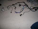
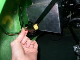
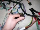
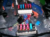
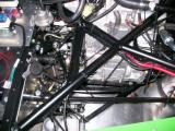
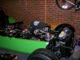
Apart from wiring the fuel pump into the loom, and running the main Westfield wiring loom in the chassis right at the beginning, I have not even thought about the electrical side of things. It's cold outside and I don't really fancy going out into the garage, so I decided to have a look at the dashboard loom and get my head around it indoors.
In the bag is a block connector kit, a few rocker switches, some toggle switches, and some warning lights. The warning lights will not be used though since we are using a digital dash which has inbuilt warning lights.
The digital dash unit comes with an adaption harness which must be connected to the standard dashboard loom. It all seems to make sense, but I can't understand how the rocker switches connect to the loom. I can't see anywhere for them to fit. I'll just put it all back in the bag and ring Westfield.
Laurence
 |
 |
 |
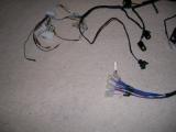
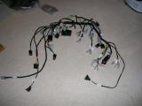
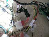
I decided to have another look at the loom. Using the loom identification tables in the big manual, I was able to work out what most of the wires were, and how they plugged into the digital dash loom. Everything is fine except I can't work out how to fit the indicator switch, nor the headlight switch, fog light switch, and the other bits that a standard dash would use. I'll ring Westfield about it as I can't see how it will work.
Laurence
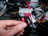
The front and rear lights all need wiring into block terminals so that they are compatible with the Westfield loom. I have bought a tool suitable for crimping the tiny uninsulated needle terminals from Vehicle Wiring Products.
http://www.vehicle-wiring-products.eu/VWP-onlinestore/terminalsnonins/noninscrimps.php
I just snipped the original terminals from the lights and followed the Westfield manual instructions. It's actually really neat how the block terminals are made up.
I started on the rear lights and repeated the process for the fog light and the front lights too. Once I'm happy they all work I'll cable tie everything out of the way.
Laurence
 |
 |
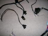
I spoke to Mark Walker at the factory today and told him about the loom. He asked me to send him a picture which I did, and he quickly confirmed that I had been sent a racing loom, which has no facilities for windscreen wipers, heater controls, indicators, the list goes on...
It's near impossible to make this fit a road car and they can't understand why it has been sent to me. The problem is I have taken quite a bit of time labeling it up and now it has to go back :(
I have asked them to get the standard loom and more of our outstanding parts out to us next day.
Laurence
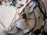
The correct wiring loom arrived today along with a couple of other outstanding parts. Immediately I can see the difference in the looms, and how the rocker switches connect. I started to label up the new loom but didn't do too much else on it this evening.
Laurence
 |
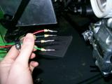
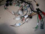
I spent a few hours finishing the loom labelling this morning. Once I had done this I adapted it to the Race Technology Dash2 loom. One of the wires pulled out of the loom so I had to make a slight modification, but it didn't cause any major set-backs.
The tachometer comes in the form of a block terminal, but the Dash2 loom uses spade connectors, so I made up a new block terminal to fit the existing tacho block, and then I ran cables out of it with spade terminals on each. These fit to the Dash2 loom, and I didn't have to cut any wires - neat!
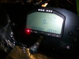
The dash wiring was really easy to complete when I got out to the car with it. It just connects to the main loom using a couple of large block connectors. We put the dashboard in place by hanging it over the steering wheel, and then just connected each of the switches to the dash loom. The labelling made things very easy, and I would recommend doing it. It should also save a lot of hassle if I ever need to do anything under there again.
It's jumping a bit ahead, I couldn't resist testing the electronics out, so we connected just the loom to the battery and flipped a few switches. The horn was the first thing I tested and it was on slightly wrong, so I altered how the earth connected and it worked. It's the biggest "Noddy horn" you've ever heard, but I was so excited about it. It's the first breath of life from the car really.
The headlights work, and so do the hazards and indicators. I can get sidelights, and I can get main beam, but not dipped beam. Also the rear fog light wasn't working either.
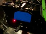
We've come this far, so we might as well go one step further and plug in the Dash2 unit. It looks AWESOME!
Have to pack up early afternoon though as we're all down in Guildford tonight for a night out.
Laurence
 |
 |
 |
 |
When I left the car on Saturday we had no dipped beam, and no rear fog-light. Also, the switches didn't illuminate when the headlights were on. Probably all related and something simple.
Over 2 hours later and I worked it out. I tried bypassing switches, I tried everything. There was no fog-light. I checked the signal into the switch which was +12v. I tried bypassing the switch to eliminate this from the problem, but still no fog light.
I was even getting power into the fuse box, but not out of it. The fuse was fine though. It turned out to be that one of the cables underneath the fuse box was not seated correctly, but I only noticed when I removed the fuse box (which is very fiddly at this stage). Fog light fixed - now for the dipped beam problem.
The dipped beam is a similar problem. The switch is getting a +12v signal, and again I try bypassing it but still no joy, so the switch is fine. Again, the switch is putting out +12v too, but the fuse is not getting any power.
I checked readings from all around the car. Eventually I decided to look at the giant block connector that interfaces the dash loom to the main loom. One of the pins that connect the block was bent and had been pushed right back and so did not seat into the other terminal. It could have been hours before I checked this as it was Westfield-made and so I didn't expect it to be a problem. I recovered the pin with pliers and once reconnected it worked fine.
Still no instrument illumination though, but that's because I forgot to connect the orange/red and black wires to each of the switches. Easy fix!
Although it was a silly problem and cost a lot of time, I really enjoyed the electrical investigation.
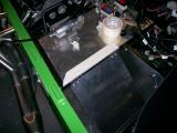
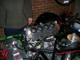
I started to look at the ECU tray. I fitted the hinges into place and drilled a couple of holes. It's getting late now though so I'll finish it another day.
Laurence
 |
 |
 |
 |
 |
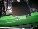 |
Tonight I wanted to get the ECU plate mounted, and the ECU into place.
The ECU plate mounts on hinges and the idea is that it can swing down to gain access by simply removing a couple of screws. I fitted the bottom part first by drilling a couple of holes in the chassis rail and then securing the hinges using M5 self-tapping screws.
I then repeated the process for the upper rail. This was somewhat more difficult though since the rail is rounded. I found it best to use the hinge holes and a guide, which made the drilling much easier. Once drilled, I used M5 self tapping screws again.
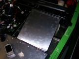
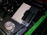
The ECU fixes to the plate using a bracket very similar to the battery tray bracket. The ECU was about half the size of the bracket though, so I decided to stick some foam onto it. This will ensure a sung fit, and also dampen the vibrations. The ECU is a really snug fit.
Now I looked at connecting the ECU loom to the Westfield loom. Westfield had already modified our loom for us (it took them 3 months though!), so I thought it would be just a case of plugging in. This is not the case though. I can't work out what should connect where, so I plugged all of the engine sensors into the loom and the electrical ancillaries to see what was left over and see if this gave any clues.
There are a few stray wires, but I'm really stabbing in the dark without knowing what to connect where, so I'll have to speak to Mark about it.
At least all of the sensors are plugged into the engine though. Every sensor will only fit in one place so you can't get this wrong. The only two that are the same are the air temp sensor and the water temp sensor, so make sure there are the correct way around. I'm fairly sure the air temp sensor has a green wire, and the water temp is blue.
Laurence
 |
 |
 |
 |
Mark sent me through a document detailing the complete list of modifications that must be carried out to the ECU loom, as well as instructions on what to connect where once the modifications have been made. I wouldn't have been able to do it without this document.
The first thing to do was connect the power cables up to the engine. The chain is very simple.
- Take the longest power cable, and connect it from the positive battery terminal to the starter solenoid (it has a plastic cover over the terminals). Connect this to the left terminal. You will need to run the power cable up through the panel where the fuse box lives, as the starter solenoid should fit on the ECU tray.
- From the right side terminal on the starter solenoid, route this back down through the panel, into the engine bay, and connect it to the starter motor.
- Now connect the starter solenoid to the negative battery terminal.
With this all taken care of, I decided to try and engage the starter by turning the key, but nothing happens. I trace through the wiring and I find out that in order to start the car, the engine must be in neutral, but I'm not getting anything from the gear position sensor.
I was playing around for ages, and I eventually find that the signal into the starter solenoid from the ignition barrel was not connected, so I manually connected the white/red cable from the Westfield loom (starter signal) to the yellow/green on the hayabusa loom. This tells the starter solenoid that the key has been turned to start the engine.
Now when I turned the key I got a massive drain on the battery (I could see it on the multimeter), but still no action. I tested various circuits, but still couldn't find out why the signal is not reaching the ECU loom from the gear position sensor etc.
I checked that the starter motor was working by touching a live cable straight from the battery to the starter motor, and it immediately whirred, so I know it works.
Eventually I work out it's because I have not earthed the ECU loom which was really silly. I removed one of the screws that holds the ECU tray into place, and secured the black/white earth wire here which keeps things very near, and saves running a cable back into the engine bay.
Now a quick turn of the key and the starter clicked into life. Apparently it is safe to do this as long as it's only very quick. There was no oil in the car though, so I did it once and left it. Now we know the ignition circuit is working, so we won't have to play about with wiring next time, except for making a permanent connection between the white/red and yellow/green wires for the starter signal. I'll also have to connect up the RPM signal, gear signal, and fuel pump etc. but I'll do this properly next time.
Laurence
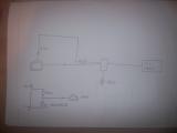
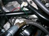
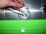
I wanted to use an oil temperature display with the DASH2, and I thought it would be very easy to use the sensor that Westfield sell. Looking at the software, asks for the input voltage of the sensor at various intervals. The problem is that the Westfield VDO sender gives a varied level or resistance and not voltage.
There is a way around this though. In order to use a thermistor with the DASH2, you must create a potential divider. What this does is uses a known voltage output, then applies two levels of resistance to the circuit - one fixed, and the other variable (the output of the oil temperature sender). This in turn gives a variable voltage, and this voltage can be used in the DASH2. You are effectively converting resistance into voltage.
What you need to do is get the resistance levels for the various temperature points, convert them using the potential divider formula, and then use that voltage in the dash.
This link was very useful to me: http://electronics2000.co.uk/data/itemsmr/potdiv.php
The DASH2 unit has a 5v reference output, so you use this.
I used a 1k resistor for the oil temperature, so if for example my resistor gave out 300ohms when the oil temperature was 10C, you would do V2 = (R2 / (R1 + R2)) * V1
V1 would be 5v, R1 would be whatever resistor you fitted inline with the 5v feed (1k in my case), and R2 would be the resistance that the sensor gives at 10C.
This would give you 1.154V, so you would set your channel output in the DASH2 to read 10C at 1.154V, then do the same for 20, 30, and so on.
Look at the images below which should show you how to create the complete circuit.
Laurence
 |
 |
 |
I emailed Lorne at Race Technology about the DASH2 freezing. It only seems to happen when it's not connected to the laptop.
Lorne replied and said that Westfield should have sent me a terminator that should be connected to the dash serial port when not connected to a laptop, and he has popped one in the post for me. Until it turns up, I'll just make sure I connect the laptop to the DASH2 when the engine is next running.
Laurence
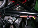
I had already begun to create my potential divider circuit for the oil temperature sender, but I hadn't connected it up.
I spliced into the gray 5v reference wire on the DASH2 harness, then connected a cable with the resistor (made earlier) to the 5v cable. From this point I then ran a cable to the oil temperature sender, and the other to the aux channel I was using for oil temperature. So the aux cable joins between the two resistors (one being the oil temp sender).
Once done and working, I wrapped the whole lot with lots of heat shrink and electrical tape.
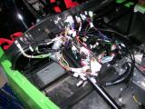
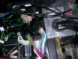
Now with all wiring complete I could begin to tidy the engine bay by securing the cables to the engine bay. I started from the very front of the car, and worked my way back. I have a bag of 100 cable ties, and I think I'll be using plenty of them.
It looks like this will be a pain, but starting from one end makes it much easier. I didn't do any of them tight so I could always pull cables through more if I needed to. To get things tidy is quite time-consuming, but I really don't mind because I want it to look tidy under there.
I did half of the engine bay, but I'm stopping here for tonight.
Laurence
First job today was fitting the reverse light. It's just a case of positioning the light, drilling 2 holes to poke the studs through, and then soldering the wires into place within the light.
Once this was done, I did some more of the cable securing in the engine bay to keep things nice and tidy.
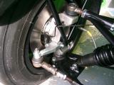
I had read on a few other build diaries that the water temperature sensor needs earthing or it will not work, so I spaced the sensor up with a couple of washers, and fitted a ring terminal beneath it which connects down to an earth point (starter motor earth).
I finished up by fitting the air filter into place with the help of Matt as it's quite difficult to do with only one pair of hands.
Laurence
 |
 |
 |
 |
 |
 |
 |
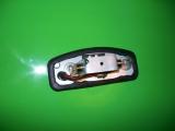
The speedo pickup normally fits at the rear of the car, but Westfield have had little success with the speedo sensor and the DASH2, so they have sent me another one with a bracket that fits at the front of the car. The bad news is that I have already secured my wiring and now I'll have to run this along the car too, but it's not the end of the world.
The sensor came with no instructions and 3 bare wires, so I had no idea what to do with it. I spoke to Mark at the factory and he told me that the wires just needed soldering into the speedo block connector on the dash loom. I could see it had worked because the sensor unit lights up orange when it sees a connection. I just had to adjust it to sit close to the hub bolts and then it was all done.
Laurence
 |
The car has been out and about quite a bit now, and there is something strange going on with the sensors. I have checked the configuration and my maths over and over again and I still can't work out what the problem is.
I am one of the first DASH2 users, so I'm pretty much on my own when it comes to the configuration. I have managed to get the PDF files from VDO which document the resistance curves for each of the sensors, as well as their associated temperatures/pressures. Mark Walker has also send me the wiring diagram for the DASH2 loom, which shows that 910ohm resistors are used to create the potential divider circuits. I have everything I need, and I'm sure my spreadsheet to calculate voltages at the various points are correct too.
It turns out they are, and the DASH2 is dead accurate when everything is switched off. However, when I switch on the engine the values immediately jump up. 80c on the coolant temp will jump up to 95C just like that, and fuel level will also change!
It's a real head-scratcher, and Westfield say they have not seen anything like this before.
I have spoken to Race Technology about it too, and between us we think it sounds like an earthing problem. The more load you put on the car (e.g. engine running, main beam, fog lights, indicators, cooling fan etc), the higher the readings will go. There must be an earthing problem somewhere and current is being back-fed. I have followed the Westfield wiring instructions perfectly though.
I turn to the Westfield forum for help: http://boardroom.wscc.co.uk/cgi-bin/ikonboard.cgi?act=ST;f=3;t=63538
Laurence
I have been in contact with Lorne at Race Technology about the sensors that change in value depending on battery load. Has has suggested a few different things.
I have tried changing the potential divider resistors from 910 ohm to 150 ohm which makes the problem better, but the problem is still there.
I have measured the resistance from the sensors with the engine running and not running and it doesn't change, yet it does change on the dash.
I am measuring the 5v reference feed and it's 4.96v which is right on the money. It's the same with the engine on or off! I just can't understand it, so I called up Westfield again who have asked for the unit back and they will send it to Race Technology for testing.
I have spent so long trying to get these sensor values right. These posts give only a very small summary of the work I have done checking and testing, and I'm getting frustrated with it. I'm not giving up though!
Laurence
Race Technology have tested the unit and they say that nothing is wrong with it, so it must be something to do with the wiring. Even though it;s not their fault, they are being most helpful and getting it solved which is excellent of them.
I have tried earthing the DASH2 directly on the battery but it changed nothing. Between us we're still convinced it''s an earthing issue though.
I have tried disconnecting all sensors and testing each one in isolation and they all vary depending on if the lights or engine are on or off.
I have read a post from another user who has not used the tacho feed to power and earth the DASH2 though - he has run hi sown connections and says it's fine. I am going to try this and see what happens...
Laurence
I am so glad to have got to the bottom of this one, really I am!
The DASH2 loom is powered from the tacho block connector. The 12v and GND pins are utilised from here as they are unused since the RPM counter is replaced by the DASH2 anyway. I had followed this as per the instructions.
The reason why I thought the DASH2 5v reference was stable at 4.96v regardless of engine running or not was because I was measuring with a multimeter between the 5v reference and chassis ground. This would obviously bypass any earthing problems I had and would not show up the problem.
What I should have done instead was measured between 5v reference and the DASH2 earth on the tacho block connector. When I did this it would give 4.96v, then 5.04v if I turned the lights on, 5.07v with main beam on, 5.12v with the engine running, and increase more as the load on the battery did.
So the 5v isn't stable, yet it is when measured across itself and chassis ground. So their is either an earth problem, or a ground loop where other components find the DASH2 an easier path to earth than the path they are given, which is why the 5v feed is being increased, and this is the problem. If the 5v reference is not stable then this will throw the sensors out.
I removed the DASH2 GND cable from the tacho feed and ran it directly into the chassis and then remeasured. Battery on, 4.96v, headlights, 4.96v, main beam, 4.96v, engine running, 4.96v!
I literally punched the air with happiness knowing I had found the problem - it was the earth cable in the tacho that was feeding back current all along!!!
All sensors worked perfectly except for the fuel sensor which still altered in value with load, so I took the fuel sender straight to chassis ground too and it's now completely stable too. I'm extremely happy with myself for working this out.
I have to say how highly I think of Lorne and his team at Race Technology for helping me solve this issue even though it was clear very early on that it was down to an installation issue. 10/10 for factory support.
Laurence
 |
 |