Westfield Megabusa Build Diary
Despite not being able to fit our driveshafts due to one of the stub shafts being wrong, we decided to fit the fuel system, but just not secure the tank into place so we still had lots of access to fit the shafts once they became available.
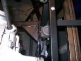
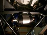
Following the Megabusa manual instead of the SEi manual, task number 1 was to fit the fuel inertia cut-off switch to the chassis. This gadget is responsible for cutting the power supply to the fuel pump in the event of a sudden impact.
Dan had come round to help us this evening to finally earn his part-timer status (and also because he hadn't even seen the car up until now). After a bit of head-spinning, we worked out where the inertia switch was supposed to be fixed, so we drilled the holes into the chassis and then secured the switch into place. Make sure you leave enough room to be able to press the switch down as there is a chassis rail directly above it! Once in place we connected it to the wiring loom as per the instructions.
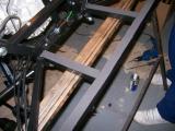
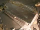
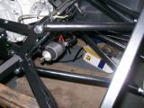
The tank is situated on the back of the chassis, but foam tape must be laid so the tank sits on a soft base rather than bare metal, because the movement could wear the tank over time. We laid foam tape everywhere the tank will be in contact with.
The same applies for the tank straps that secure the tank into place. The manual states that 1 inch tape must be used, so we just doubled up the 1/2 inch tape we had. It's easiest if you pull off the tape backing just a few inches ahead of the section that you are sticking so you can "steer" the tape.
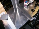
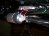
Now on to the fuel pump. The pump sits a little low for my liking, but I was only following what the manual says! You will need two people for this. It's easiest to mark the chassis and then drill right through from there, then get a second person to guide the bolt through the chassis. Also, the fuel pump has a foam sleeve which it sits inside before fitting in the bracket. Use washing up liquid get it in otherwise you'll be there all day.
Once clamped down, the pump can still move a little, but the fuel hoses will prevent this movement once connected. You now need to secure the fuel pump section of the wiring loom to the chassis and then crimp some connections to connect the pump to the loom. Once we had done this, we fixed the fuel pump nipples into place - largest at the rear (low pressure in), smallest at the front (high pressure out), and then connected the fuel pump "out" to the fuel send line, and then covered it in a plastic sleeve. There are several different types of fuel hose used for this section - make sure you use the right one!
We have left the rest of the fuel piping until the tank is fitted. Once the driveshafts have been fitted the tank should drop in without any fuss at all.
Laurence
 |
 |
 |
 |
 |
 |
 |