Westfield Megabusa Build Diary
Tonight I wanted to get the ECU plate mounted, and the ECU into place.
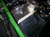
The ECU plate mounts on hinges and the idea is that it can swing down to gain access by simply removing a couple of screws. I fitted the bottom part first by drilling a couple of holes in the chassis rail and then securing the hinges using M5 self-tapping screws.
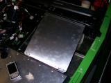
I then repeated the process for the upper rail. This was somewhat more difficult though since the rail is rounded. I found it best to use the hinge holes and a guide, which made the drilling much easier. Once drilled, I used M5 self tapping screws again.
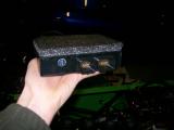
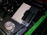
The ECU fixes to the plate using a bracket very similar to the battery tray bracket. The ECU was about half the size of the bracket though, so I decided to stick some foam onto it. This will ensure a sung fit, and also dampen the vibrations. The ECU is a really snug fit.
Now I looked at connecting the ECU loom to the Westfield loom. Westfield had already modified our loom for us (it took them 3 months though!), so I thought it would be just a case of plugging in. This is not the case though. I can't work out what should connect where, so I plugged all of the engine sensors into the loom and the electrical ancillaries to see what was left over and see if this gave any clues.
There are a few stray wires, but I'm really stabbing in the dark without knowing what to connect where, so I'll have to speak to Mark about it.
At least all of the sensors are plugged into the engine though. Every sensor will only fit in one place so you can't get this wrong. The only two that are the same are the air temp sensor and the water temp sensor, so make sure there are the correct way around. I'm fairly sure the air temp sensor has a green wire, and the water temp is blue.
Laurence
 |
 |
 |
 |